THANK YOU for purchasing The MINI F56 Oil Sender Adapter for B46 engines from CravenSpeed. This product is made from the highest grade materials and is guaranteed to be free from defects.
You can buy our CravenSpeed Tapless Sender Adapter for MINI F56LCI here
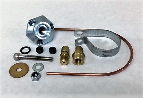
Parts Included:
- 1x Tapless Oil Adapter B46
- 1x O Ring
- 2x 1/8" NPT Plugs
- 1x NPT Male Compression Fitting
- 1x NPT Female Compression Fitting
- 1x 1/8" Copper Line
- 1x Oil Pressure Switch Bracket
- 1x Socket head screw 1/4"-20x1.75"
- 1x Locknut 1/4"-20
- 1x Large Washer
- 1x Small Washer
- 1x 24mm socket
Tools Required:
- Adjustable Wrench
- Socket Wrench
- 10mm Socket
- Socket Extension
- 3/16" Allen Wrench
- Flathead Screwdriver
- 4x Clean Shop Towels
- Teflon Tape (PTFE)
- Bunjee Cords or Straps (optional)
NOTE: A majority of this procedure involves moving around engine components and lines in order to access the oil pressure sensor. It is helpful to have some straps or bunjee cords handy in order to help keep these out of your way as you work. What is HIGHLY CRITICAL are the 4 clean shop towels listed above. You will be lifting the intake manifold off the head and potentially exposing critical engine components to a dirty environment. It is strongly recommended that you have clean and lint-free towels available to block your intake ports as soon as you remove the intake manifold.
Procedure
Accessing The Sensor
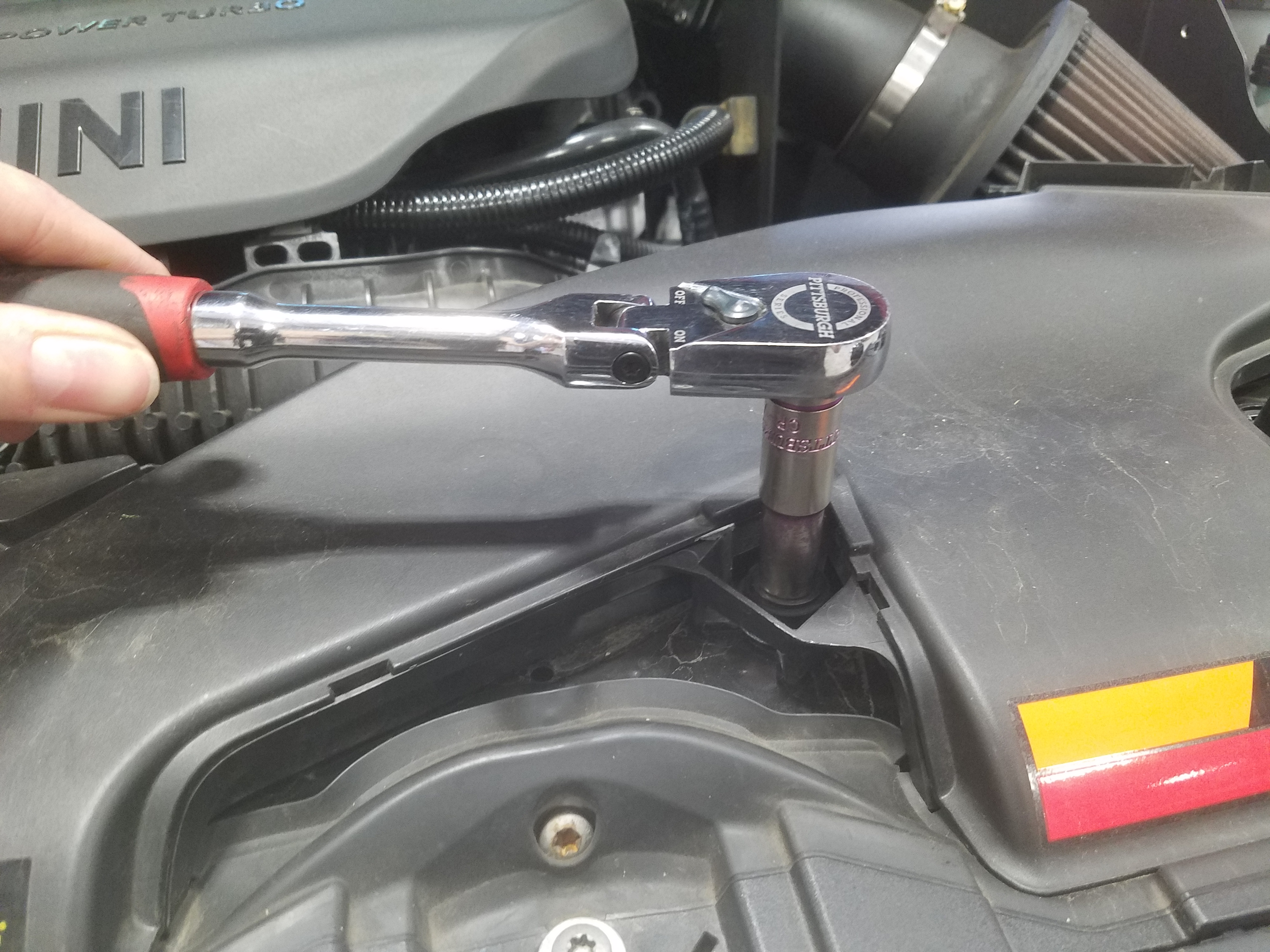
- First, we will remove the Air Intake Duct using our 10mm Socket.
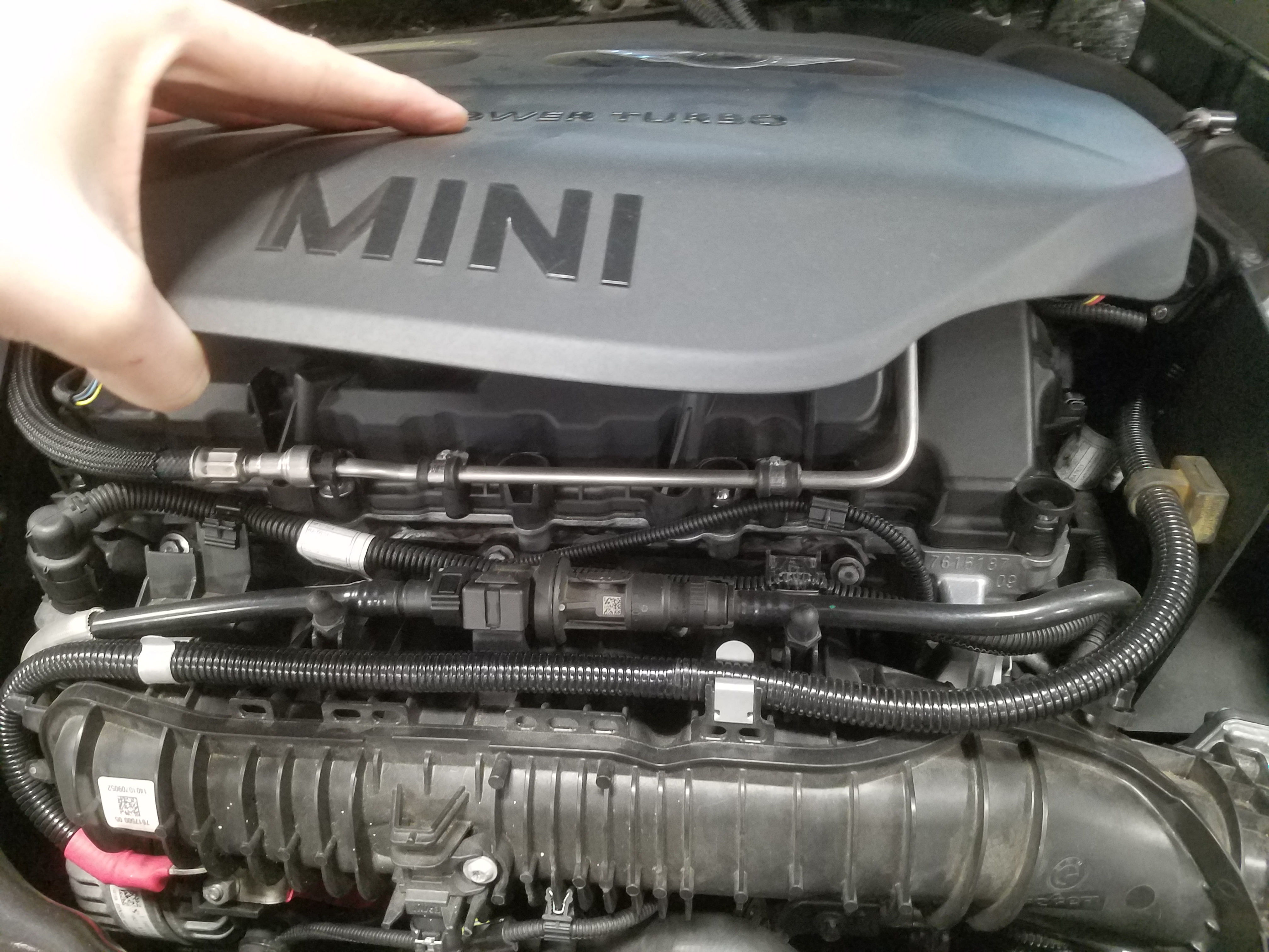
- Next, we'll pull the engine cover off.
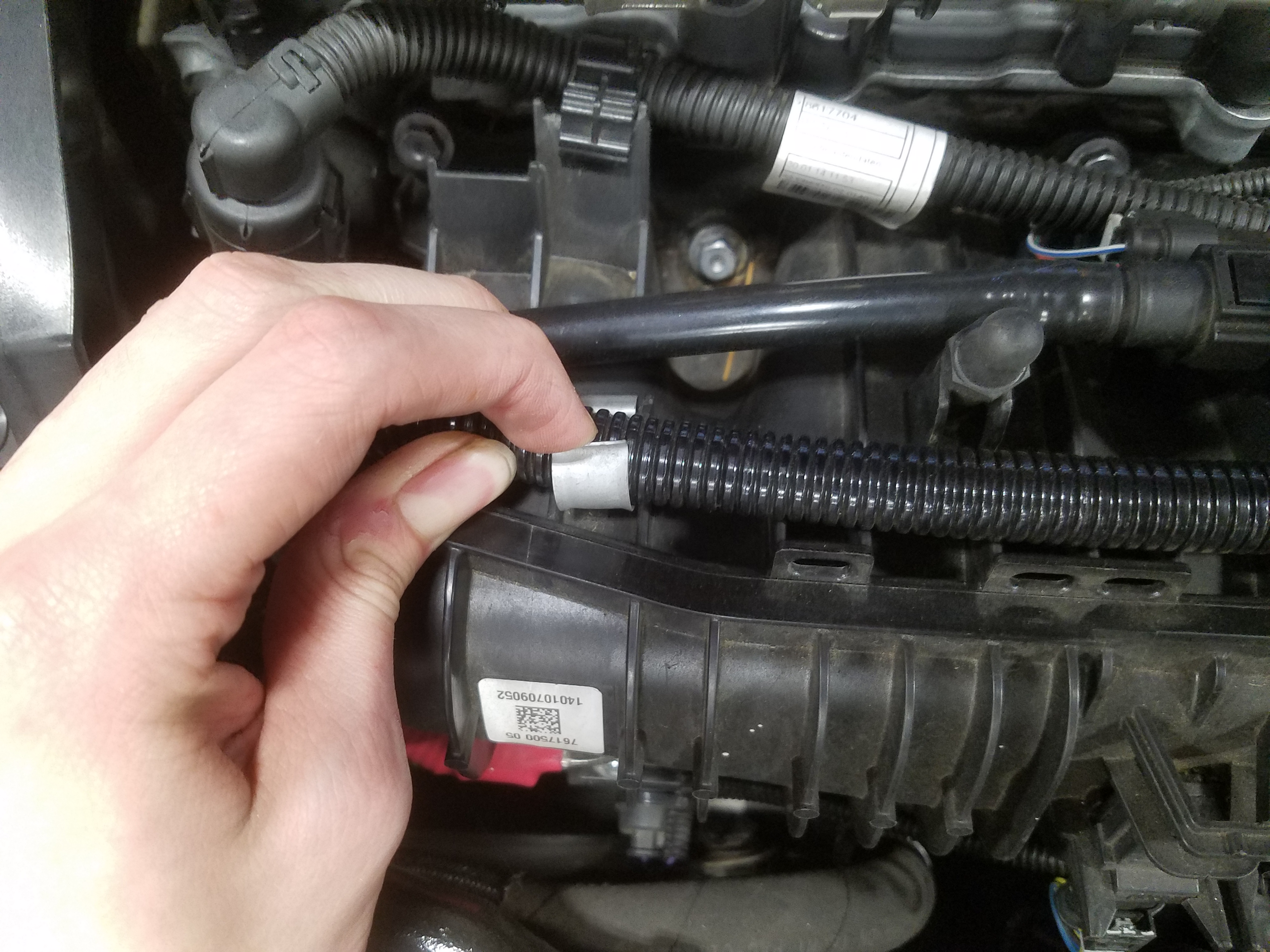
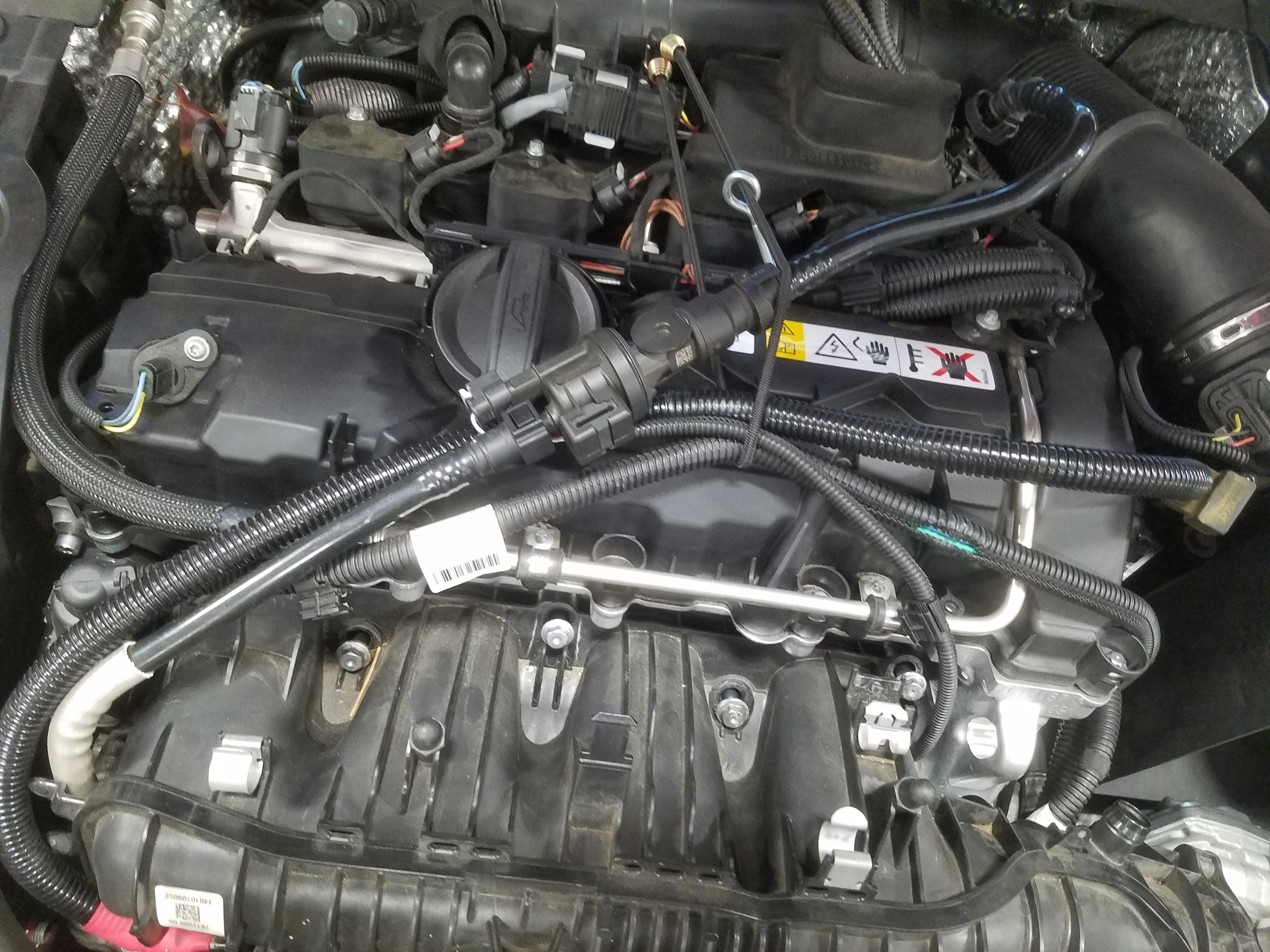
- We'll start pulling away cables and lines, starting with the alternator.
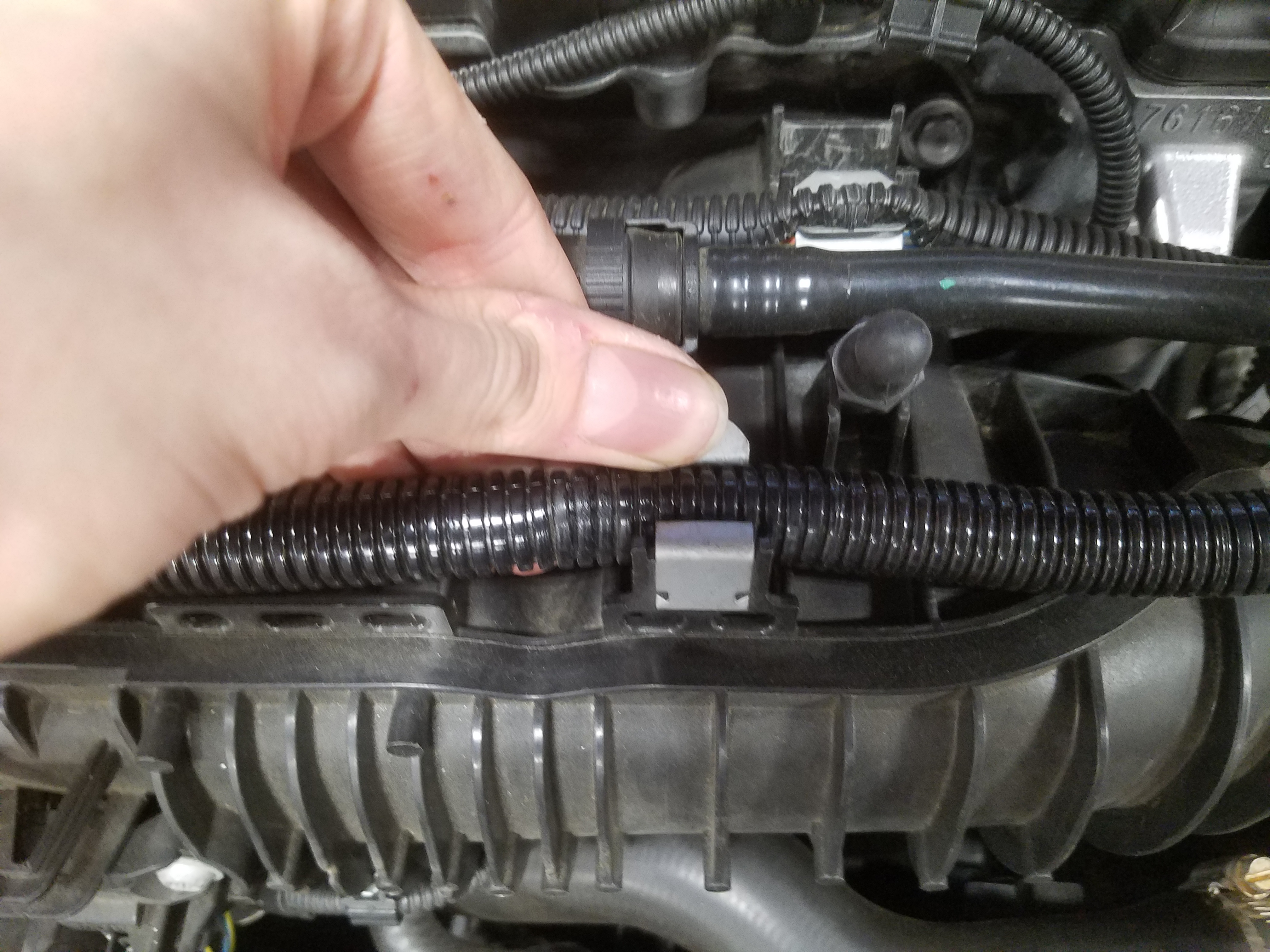
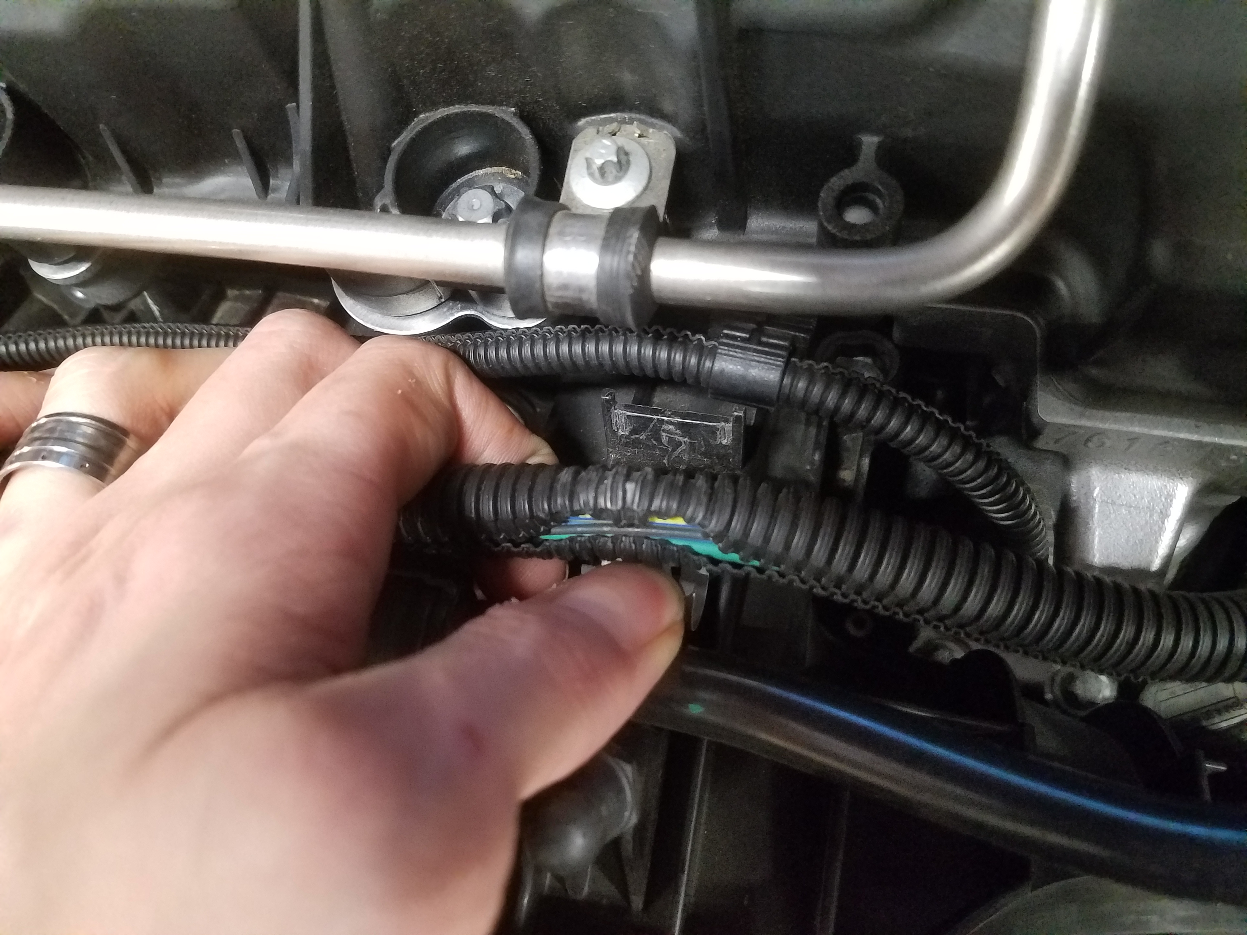
- Unclip the various lines on the top and bottom of the manifold.
- Unplug connectors.
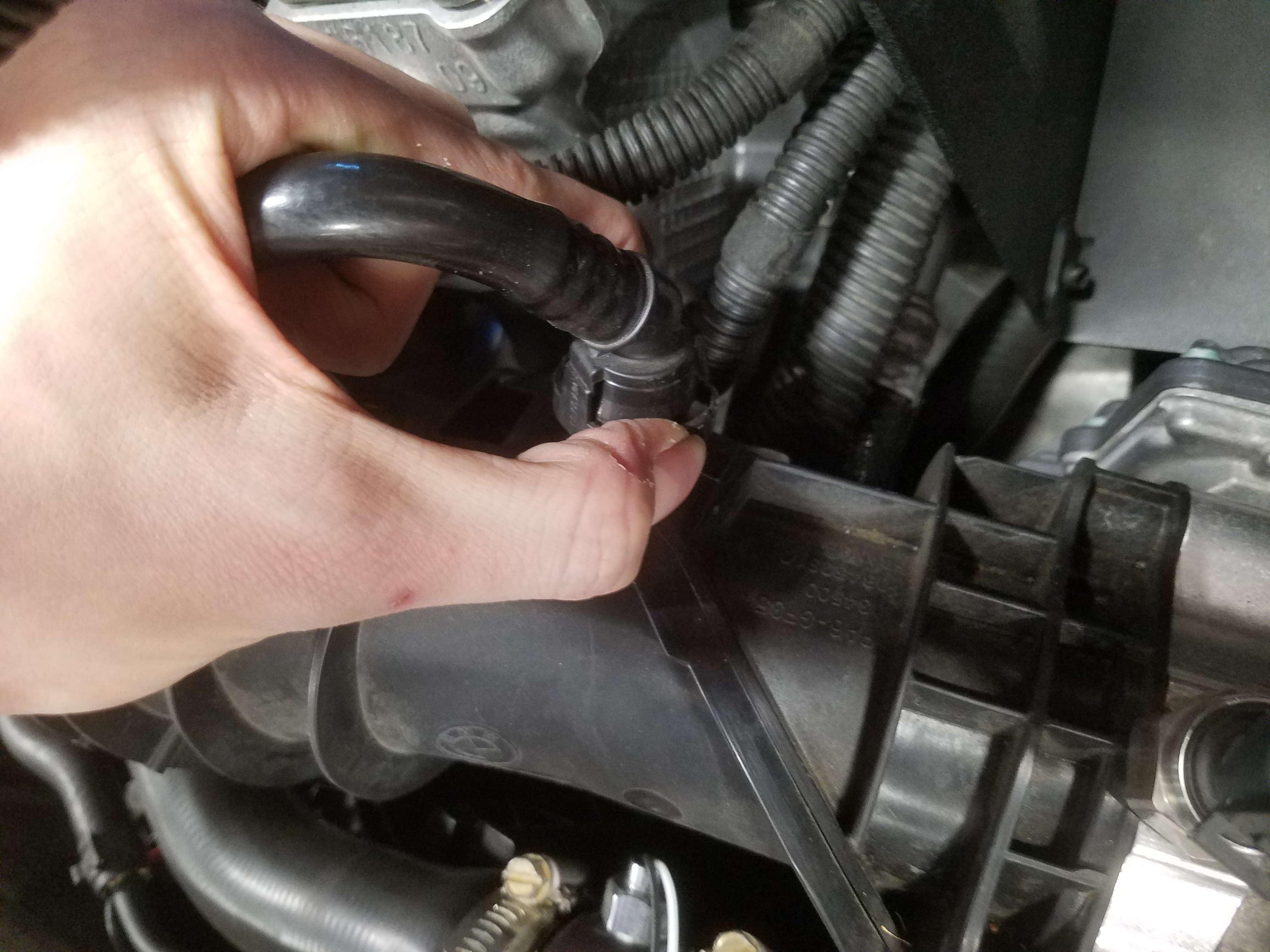
- Disconnect the breather line and pull it off the mount.
- Use a bunjee or strap to pull these lines out of the way in preparation for removing the intake manifold.
- Use the 10mm socket and extension to loosen the bolts attaching the manifold to the head.
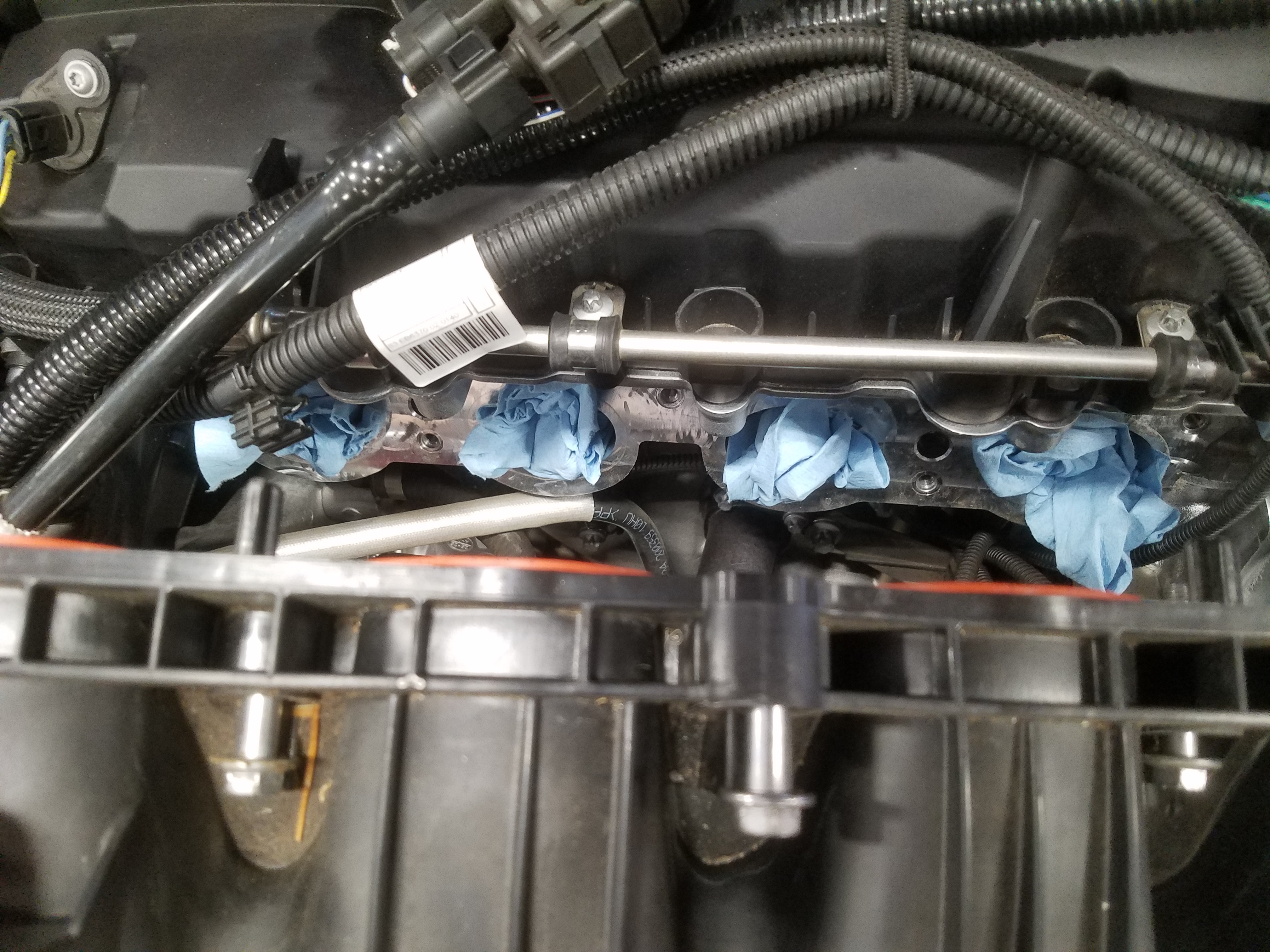
- As you lift away the manifold, place a clean towel in each of the intake ports on the head.
- Clipped underneath the manifold is a fluid line. Make sure to unclip this as you continue angling the intake manifold away from the head.
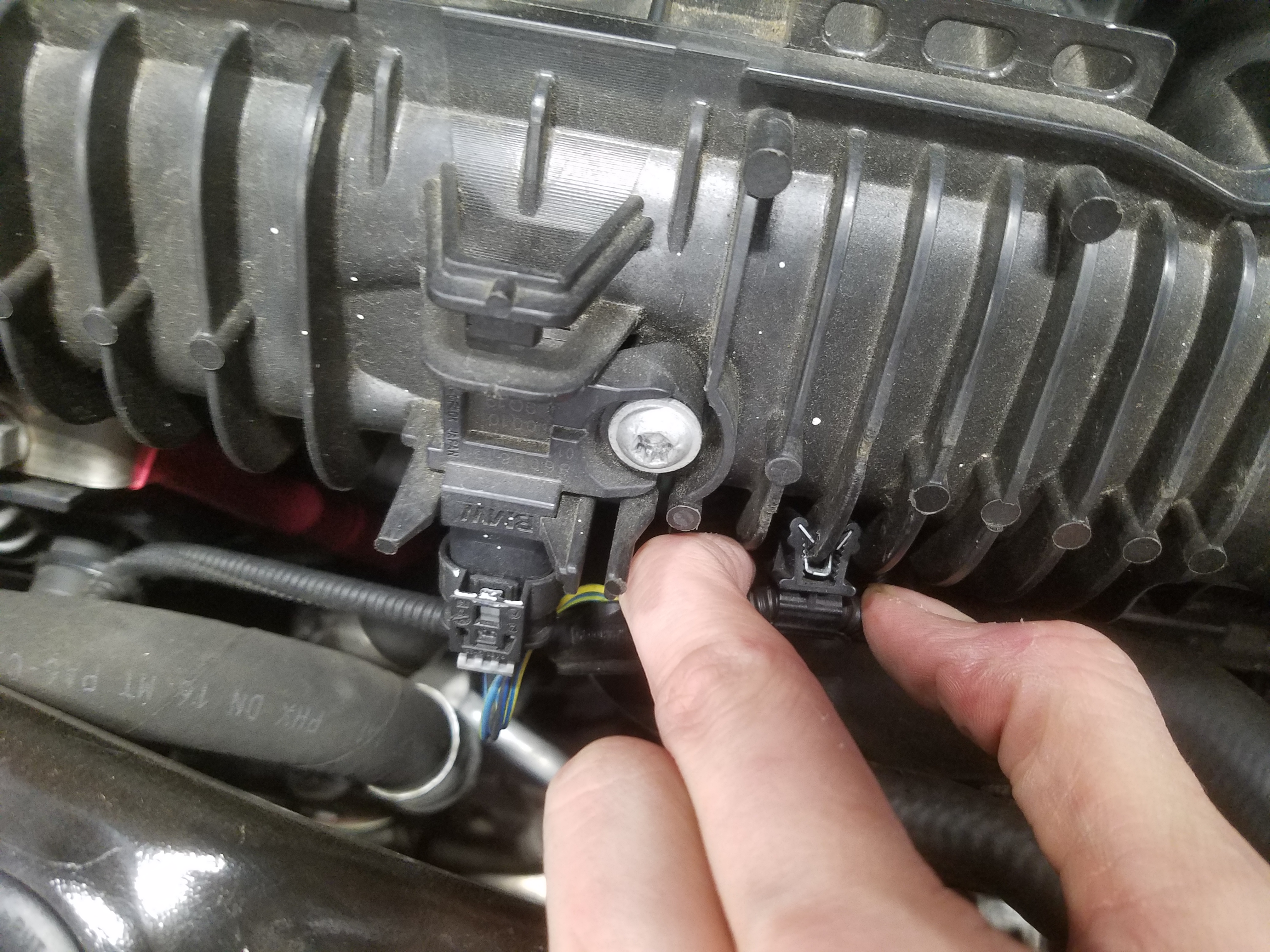
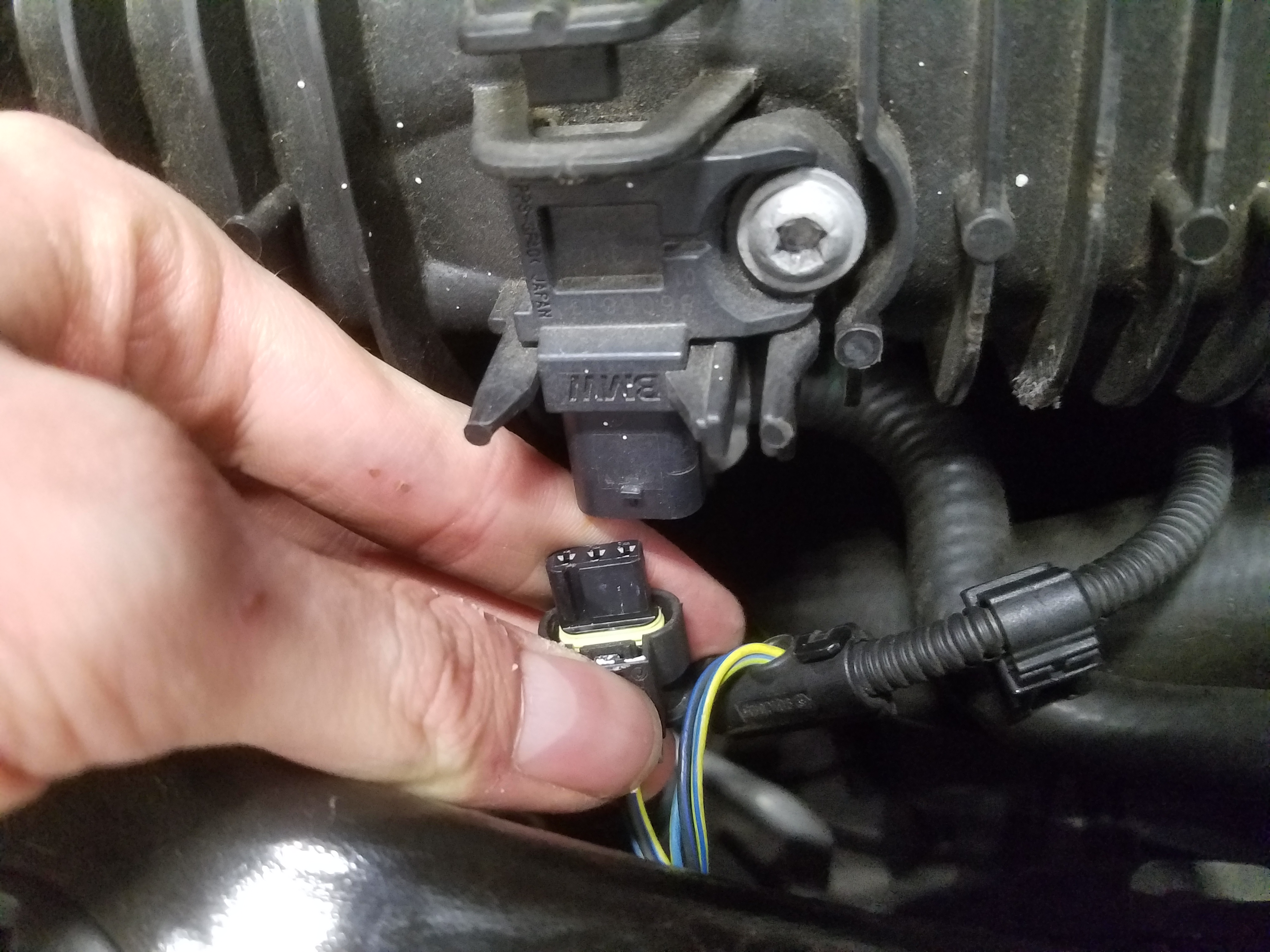
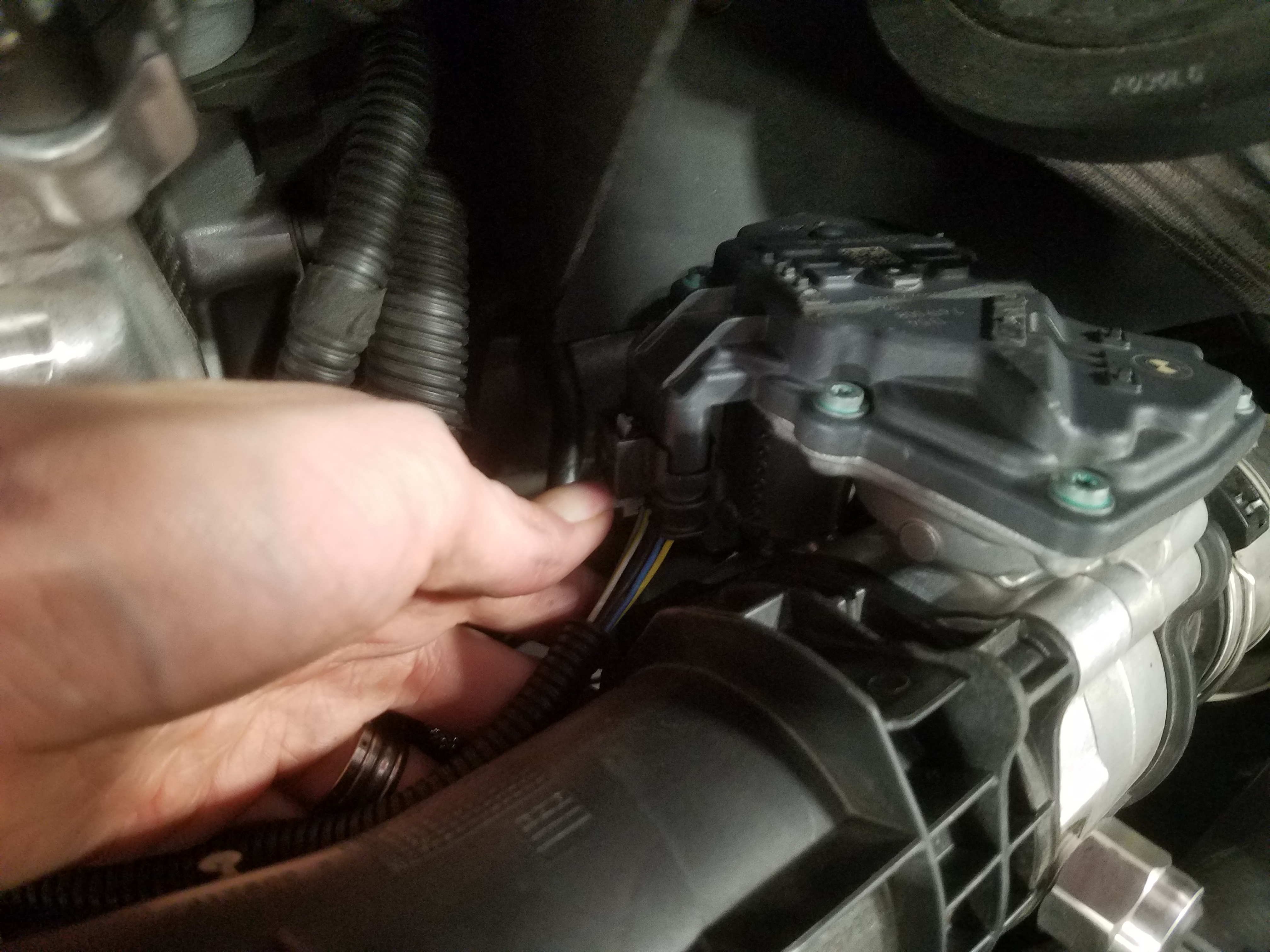
- There are two electrical connectors around the throttle body. Be sure to remove both the large and small one as you continue pulling the manifold away.
- Remove the electrical connection to the reservoir beneath the manifold.
- The reservoir itself is mounted to a tab with two circlips. Pry these off with a flathead screwdriver and set them aside.
- Using the 10mm socket, remove the bolt mounting the tab to the block, and then set the mounting tab aside.
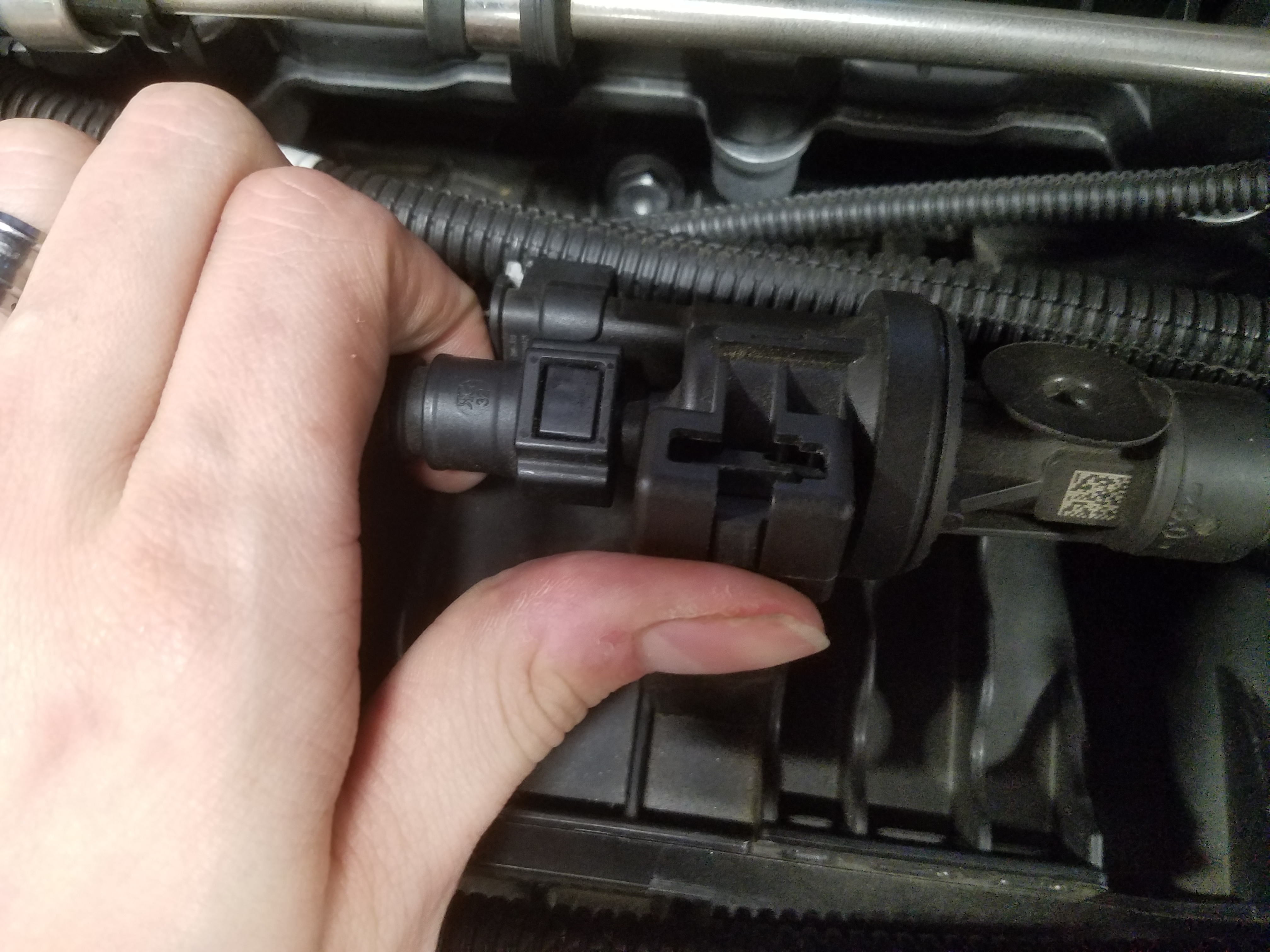
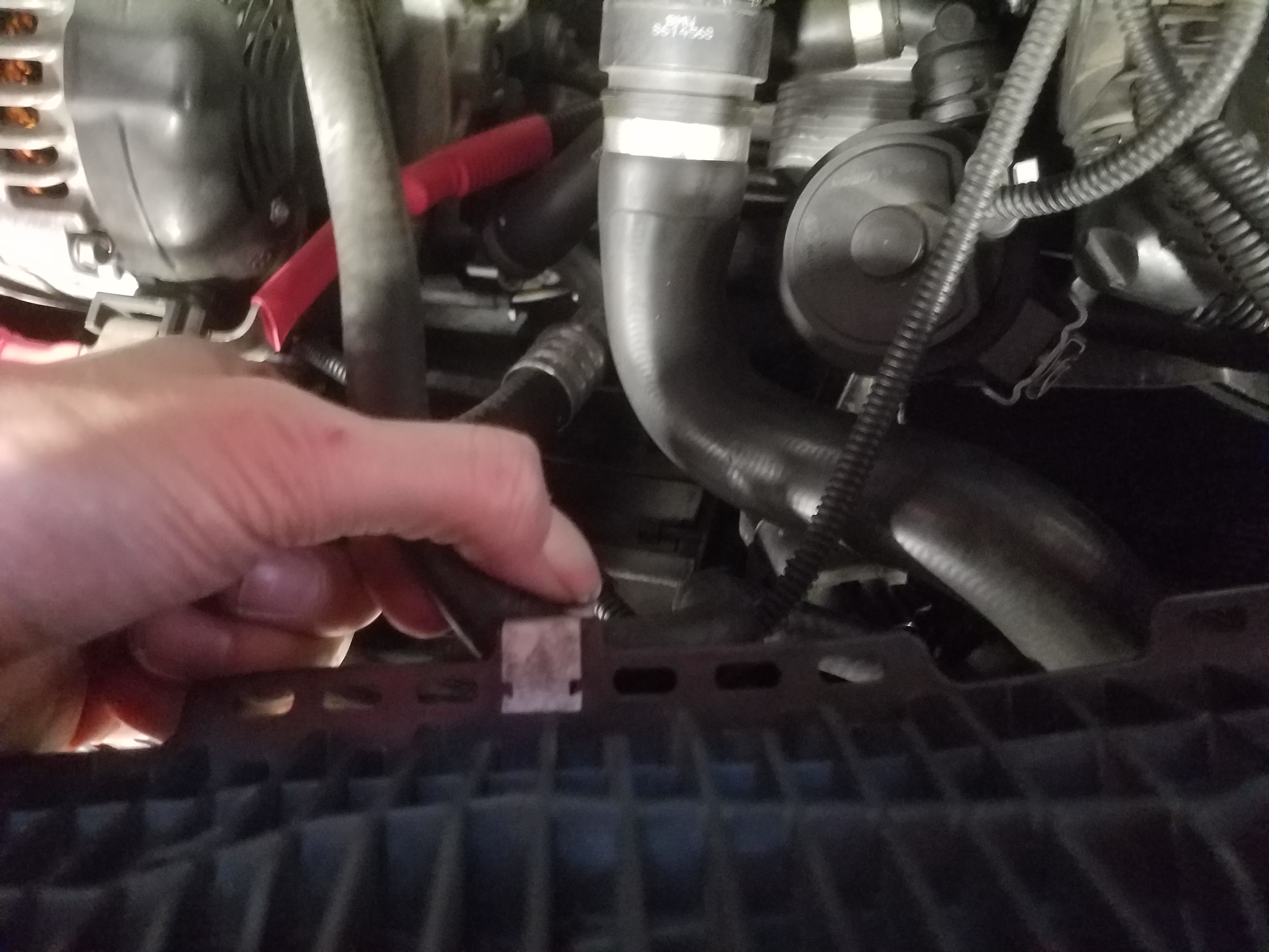
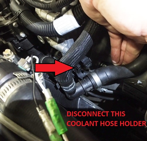
- Before prying the reservoir out of the way, there is a clip on the right hand side securing a hose. Release this clip.
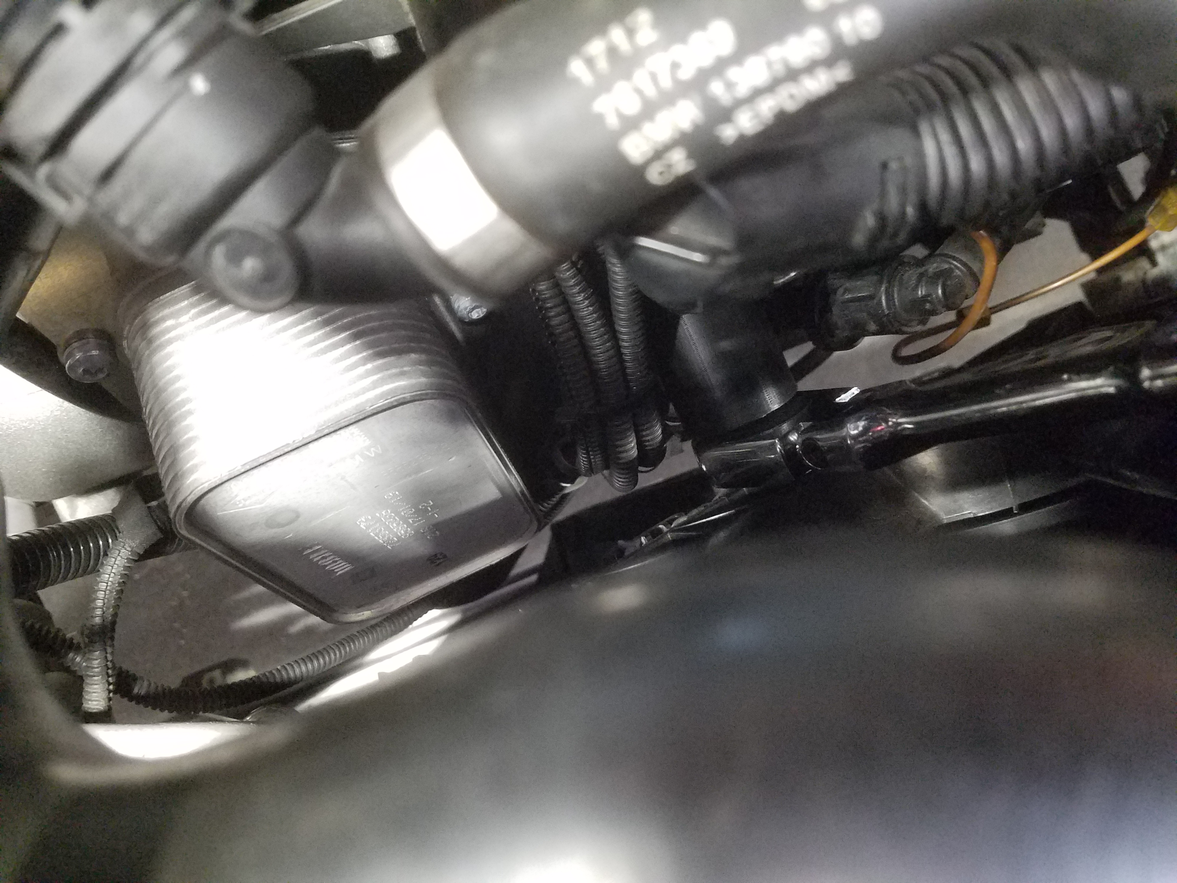
- Once unclipped, you can pull this reservoir out of the way and access the sensor.
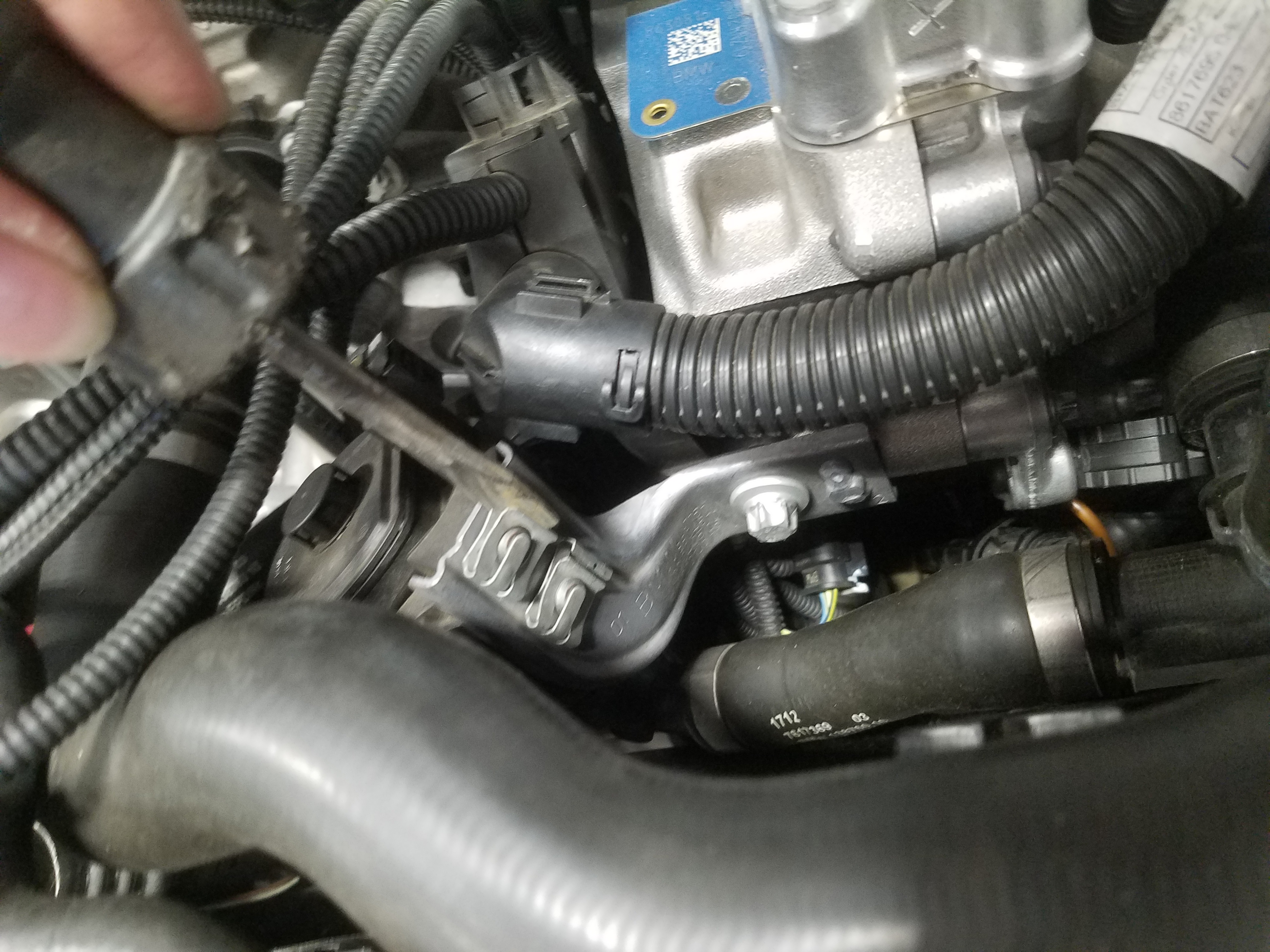
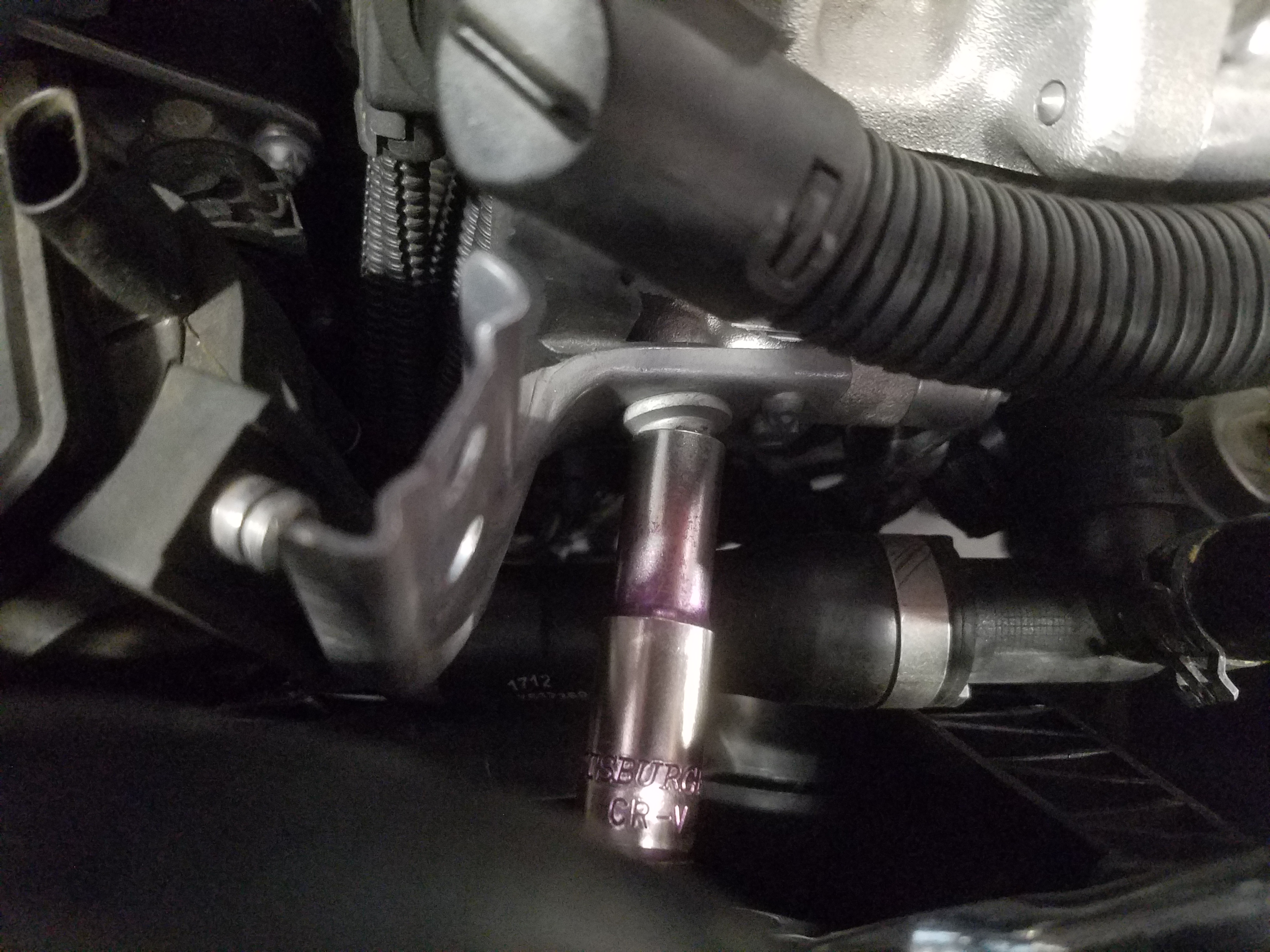
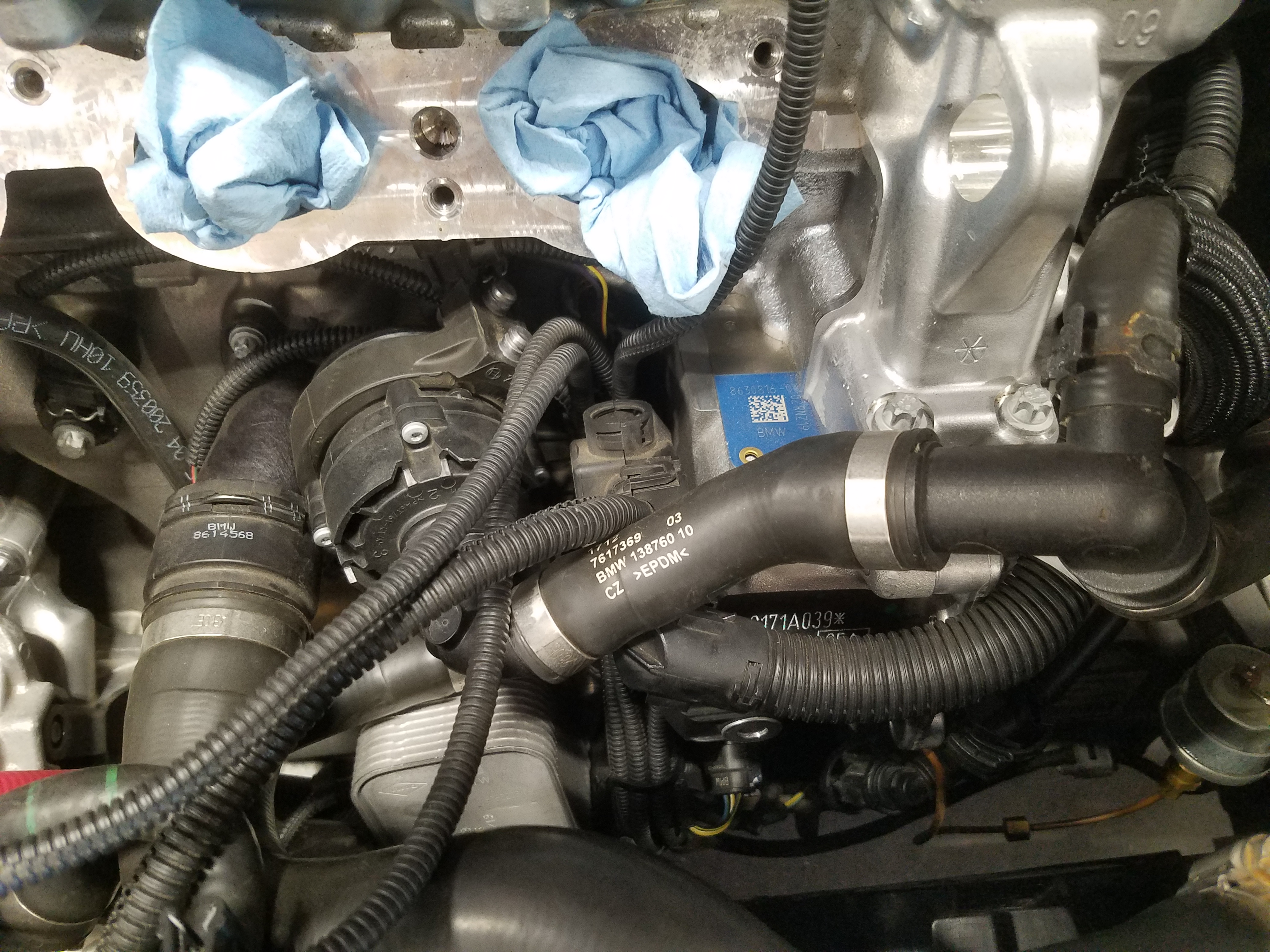
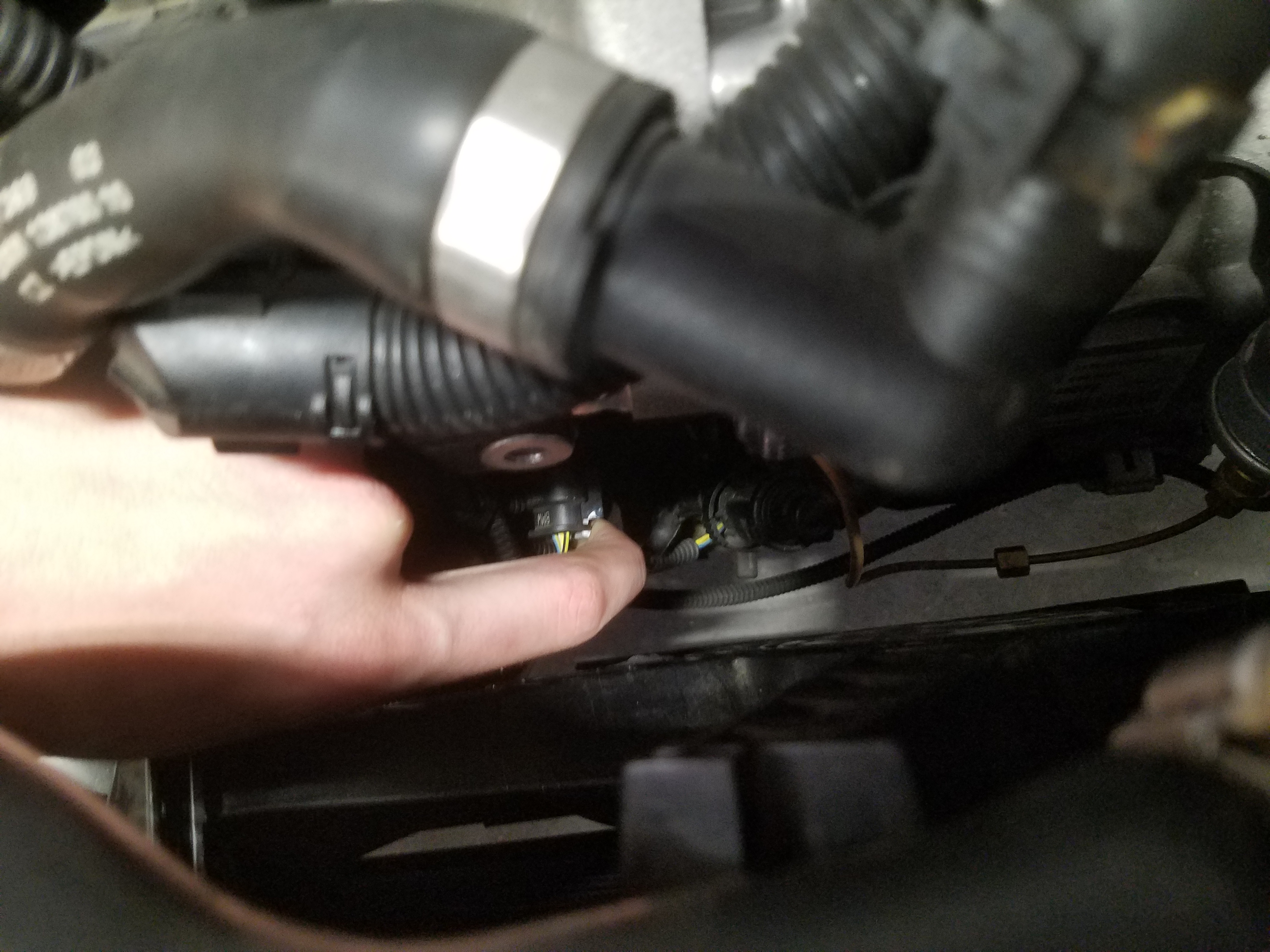
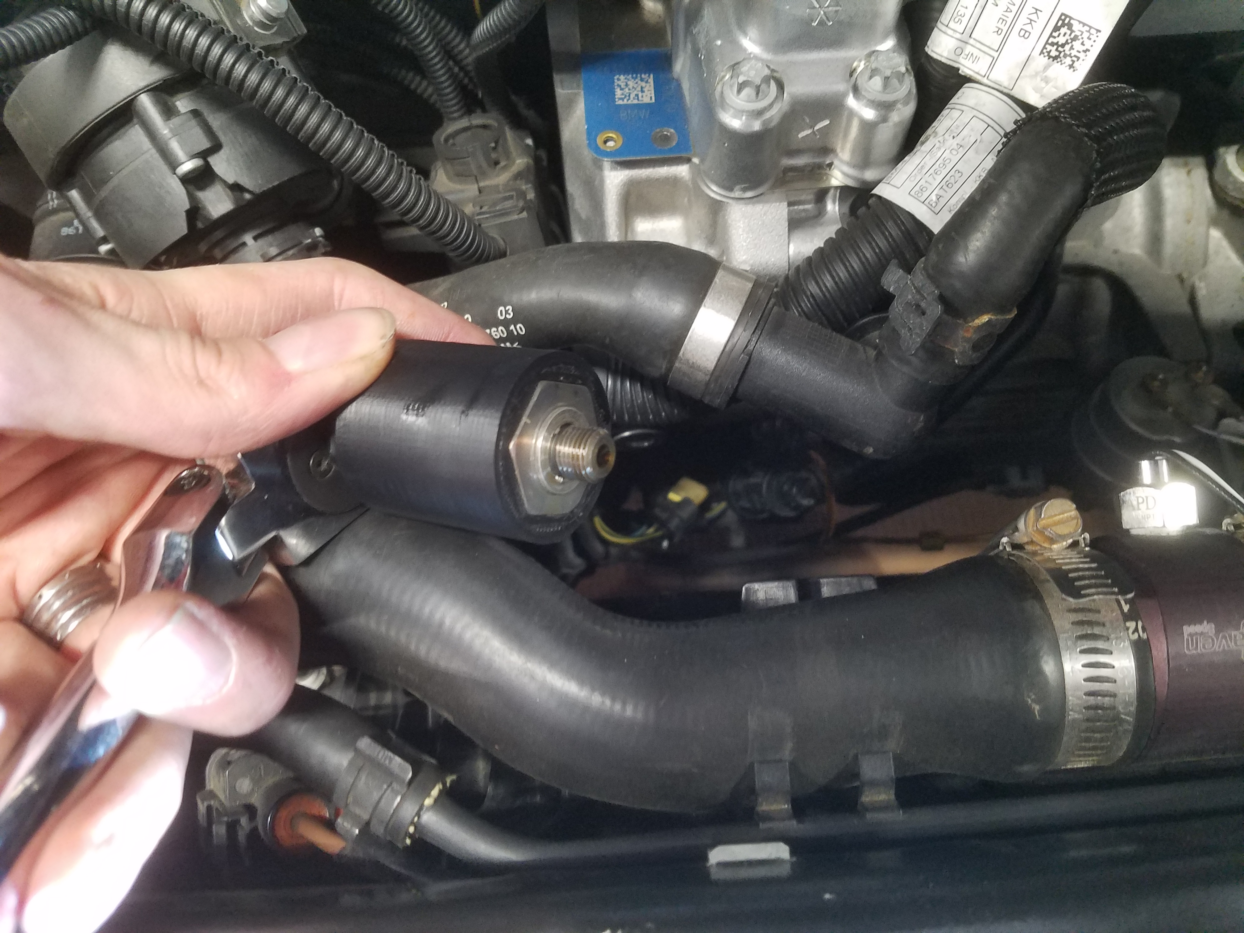
Removing the Sensor
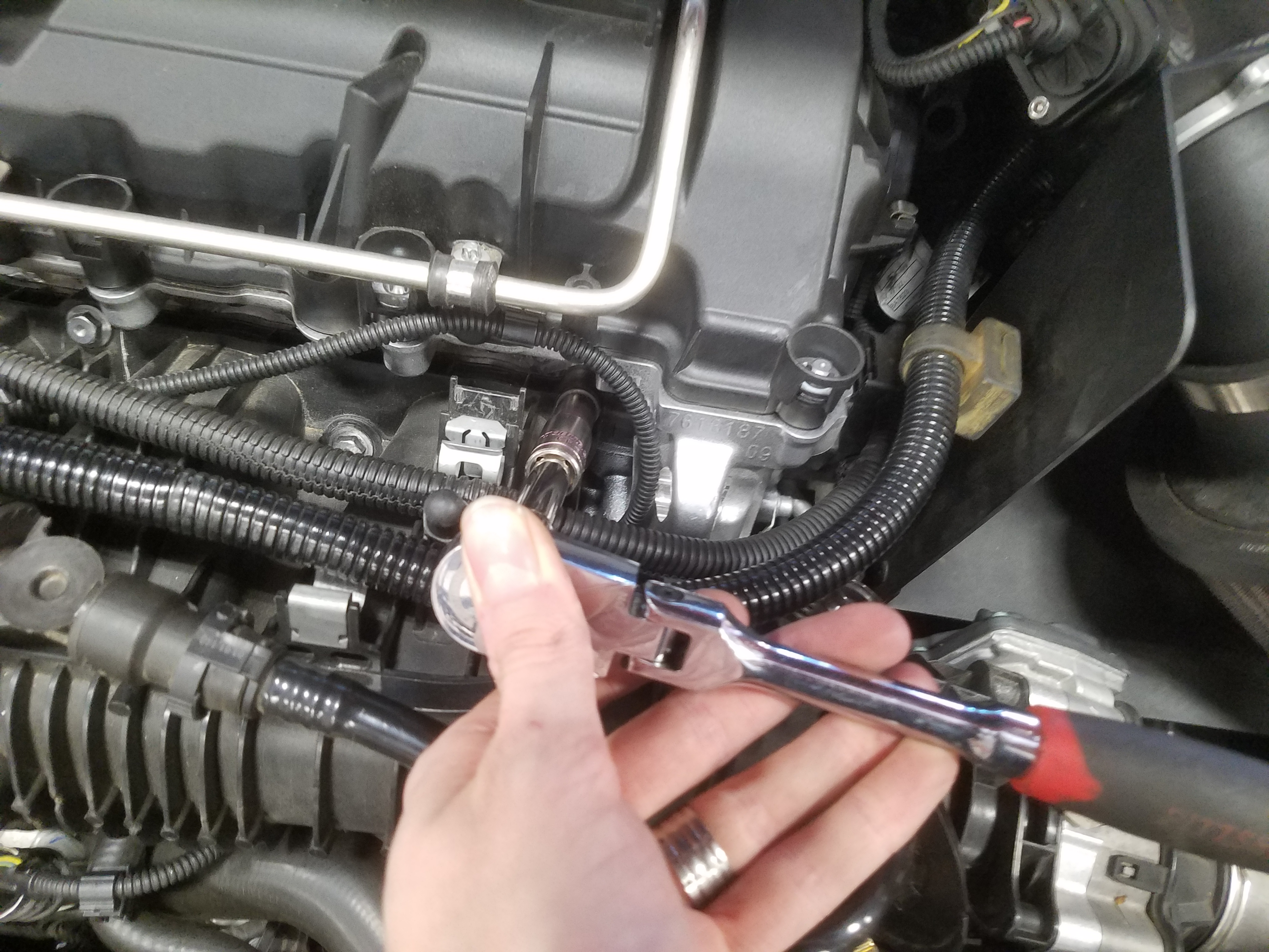
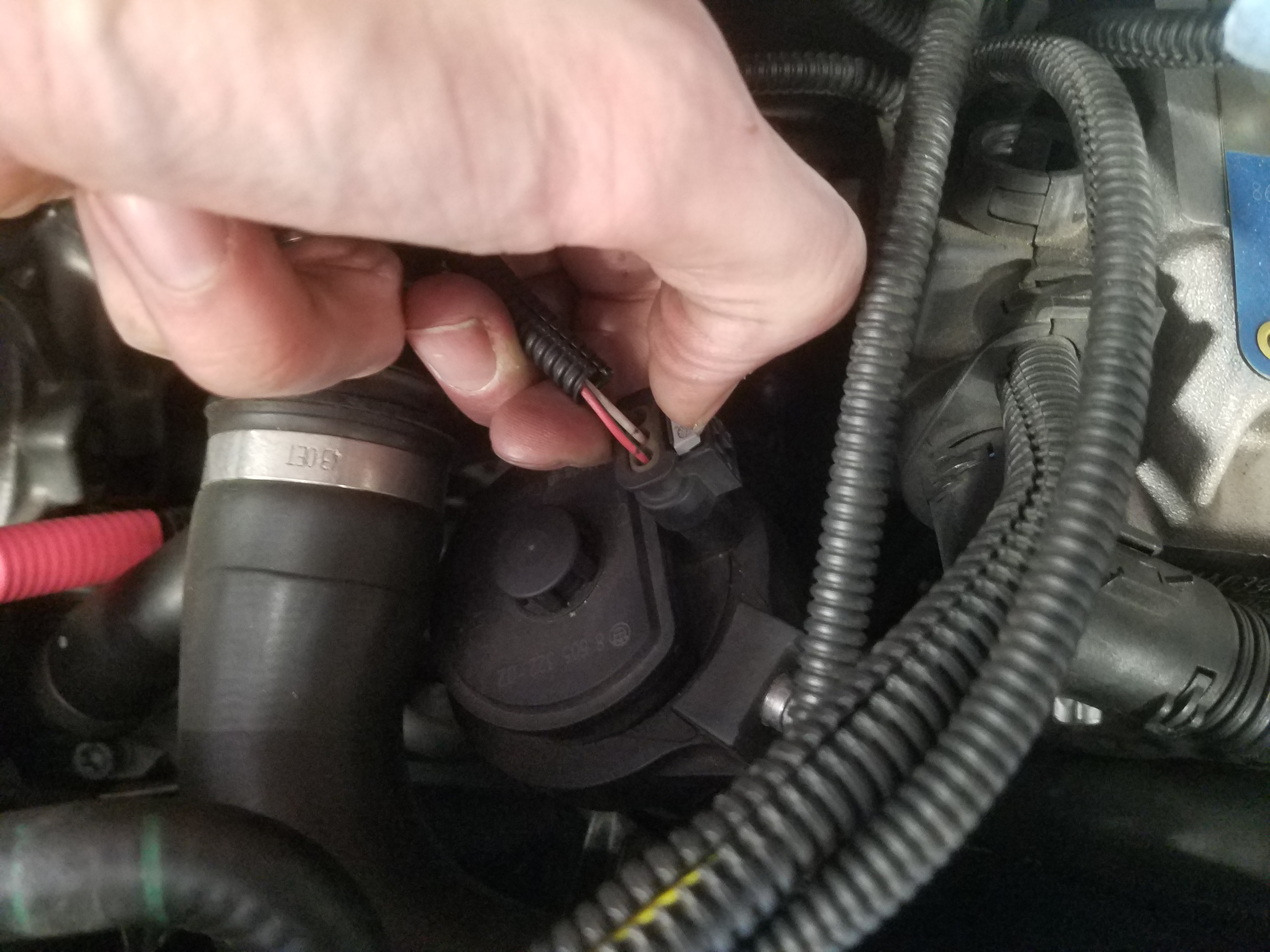
- Unplug the wiring from the back of the sensor.
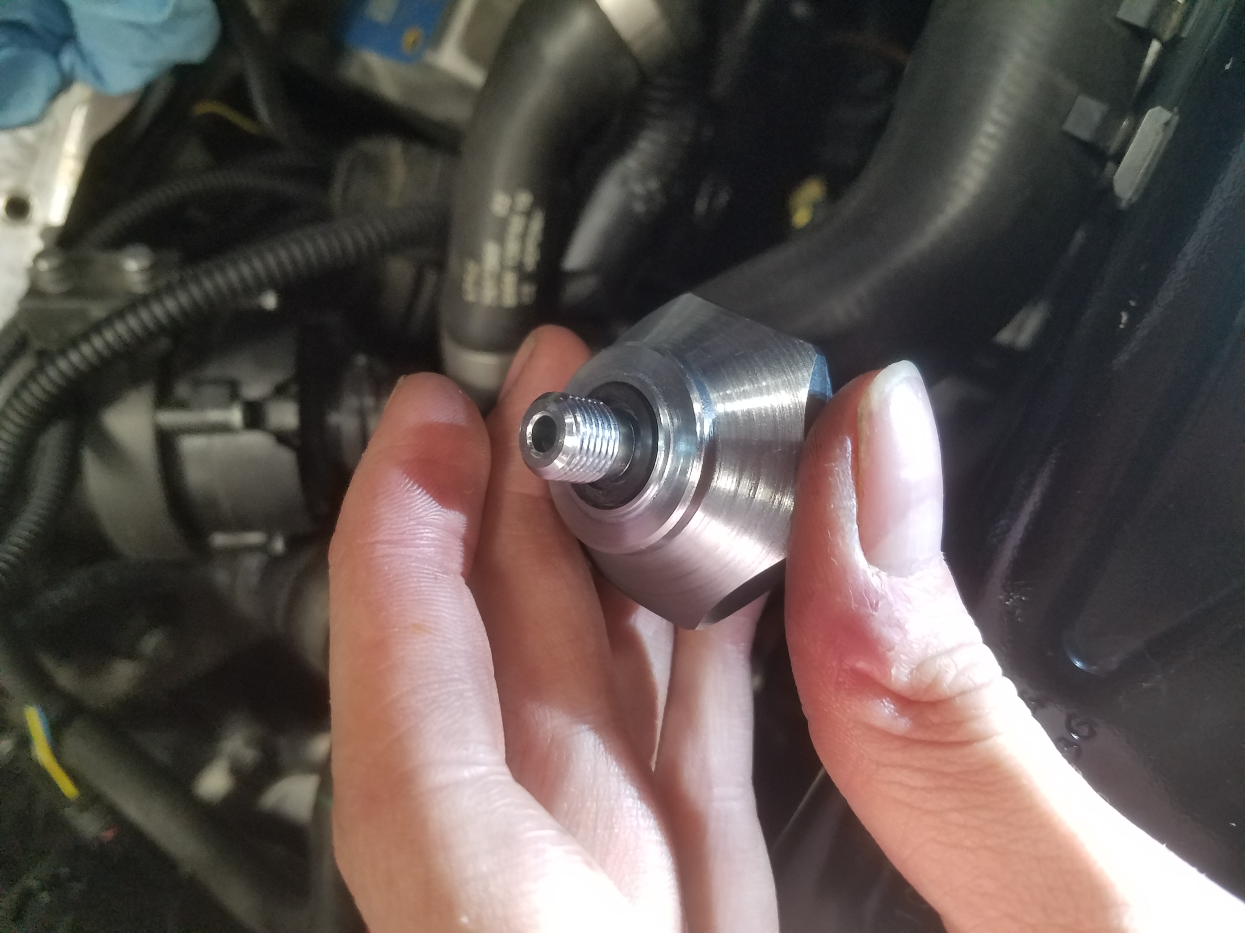
- Place the custom 24mm socket over the sensor, and then with an adjustable wrench or 24mm open end wrench, loosen the oil pressure sensor.
As you remove the sensor, a small amount of oil may drop down to the floor. It may be prudent to place a rag, small container, or square of cardboard undernear the portion of engine you're working on to catch potential drips.
Installing the Adapter
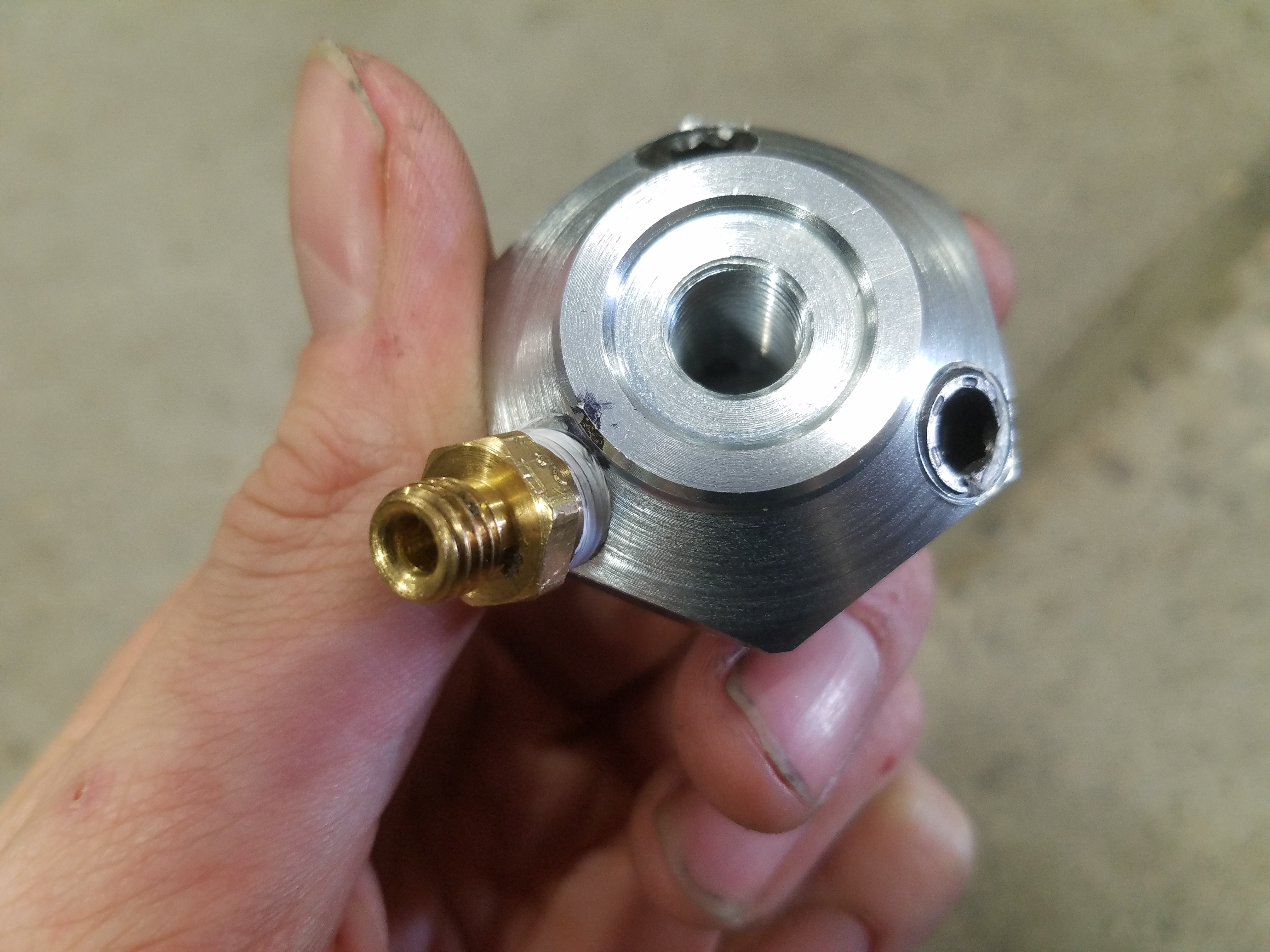
- Place the square O-ring over the external thread of the adapter, and use a small amount of engine oil to lubricate the O-ring, much like you would prepare the seal on an oil filter.
- Hand tighten the adapter onto the block that you removed the pressure sensor from.
- Make a mark on the most easily accessible NPT hole, and then remove the adapter.
- Once removed, install the two NPT set screws with teflon tape into the two unmarked holes.
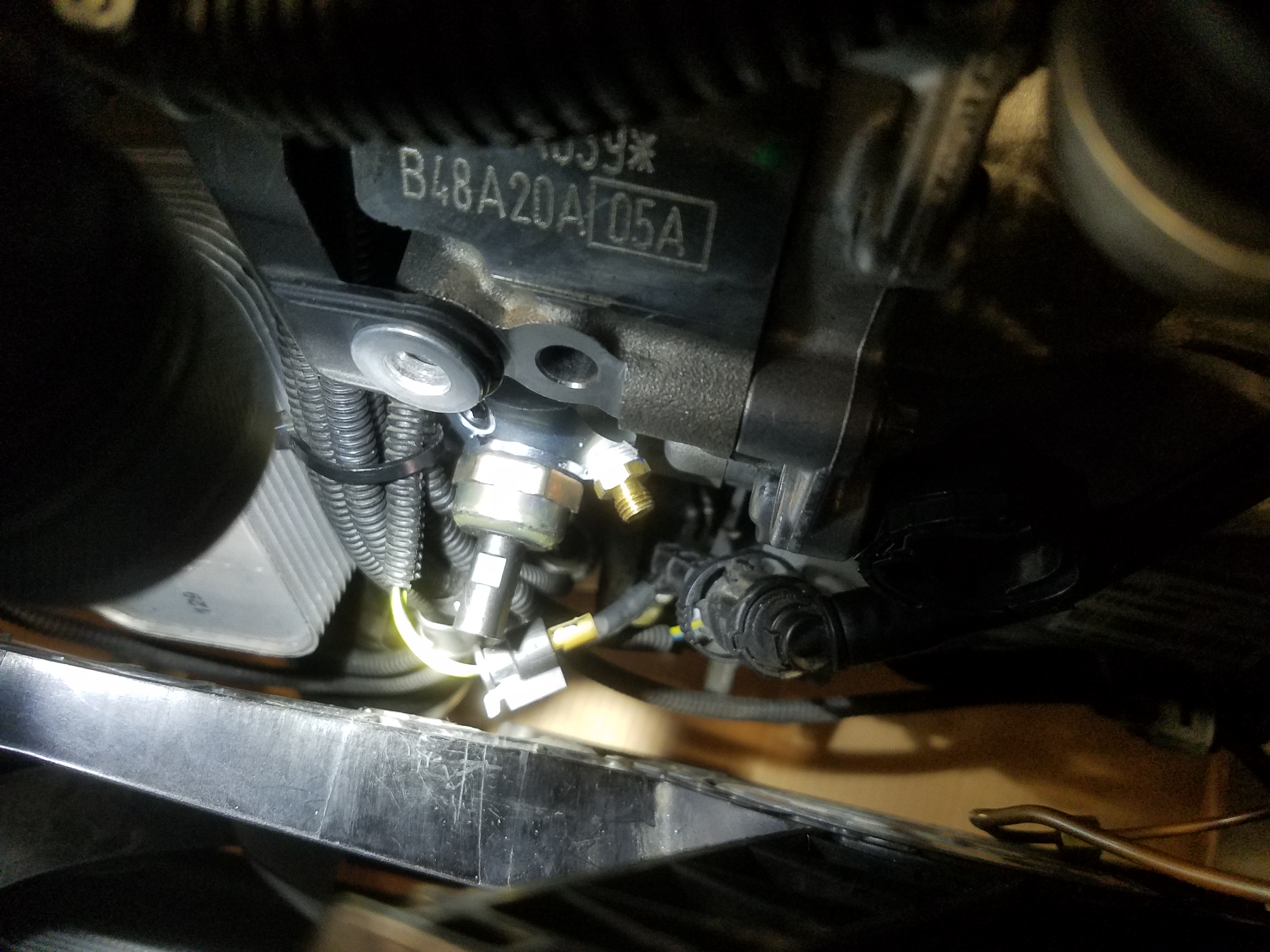
- With the hose fitting installed, you can now install the OEM oil pressure sensor on to the back of the adapter. Wire the sensor back up. Due to limited space, you may need to push on the radiator fan housing in order to complete this step.
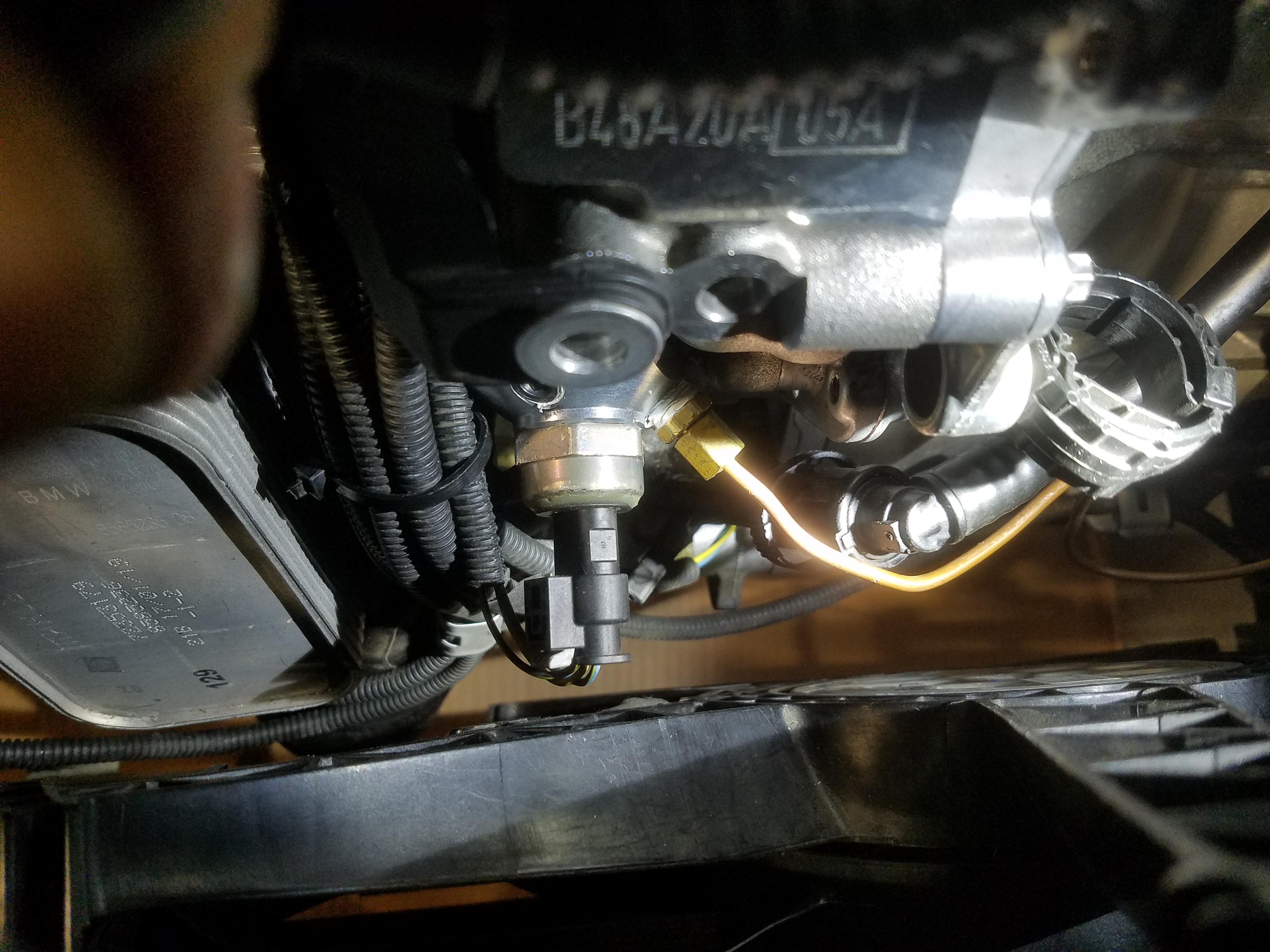
- Now we can install the hose into the available compression fitting.
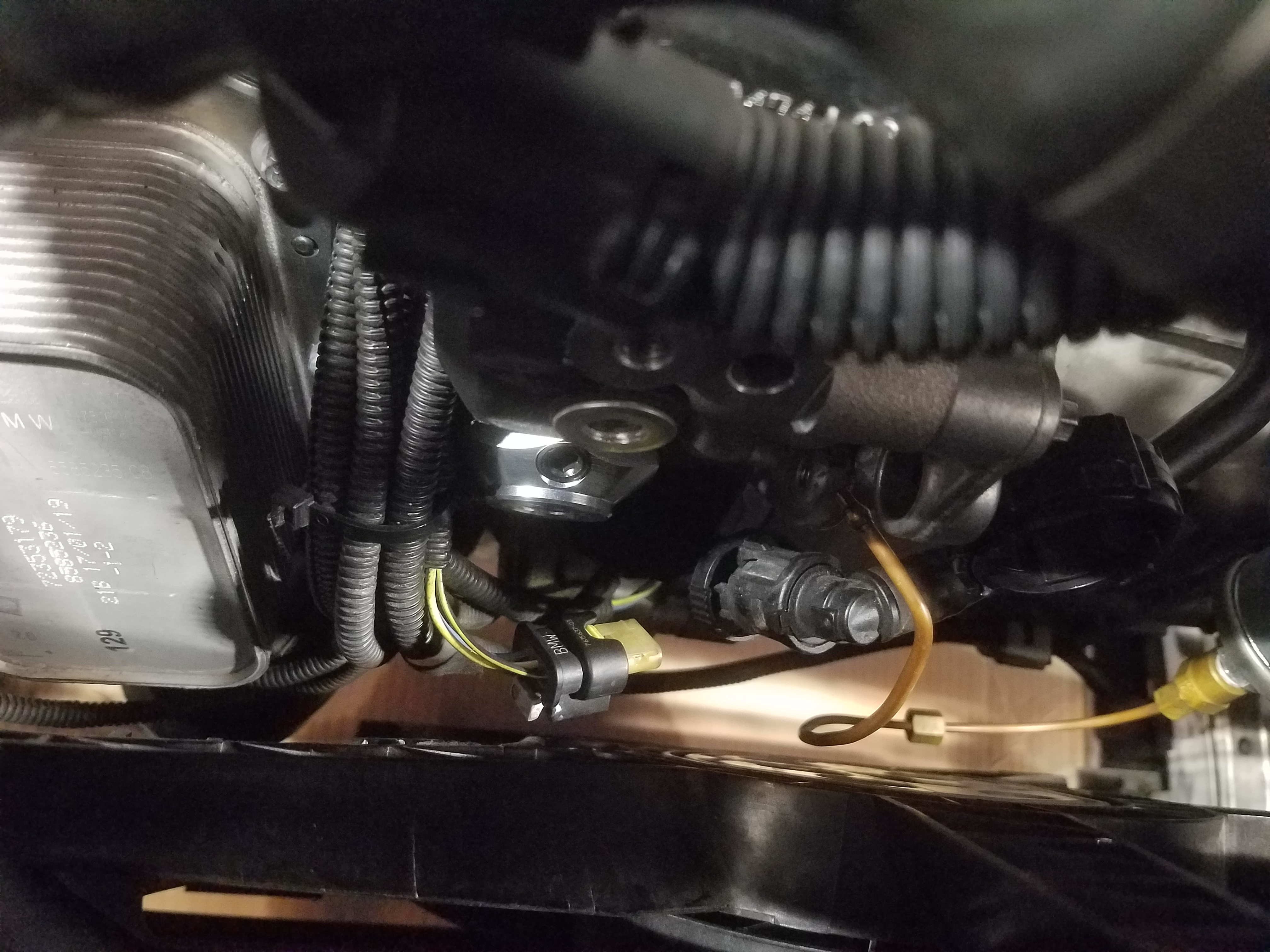
As the hose fitting will interfere with the block as you install the adapter, only install the hose fitting after you have hand tightened the adapter back onto the block.
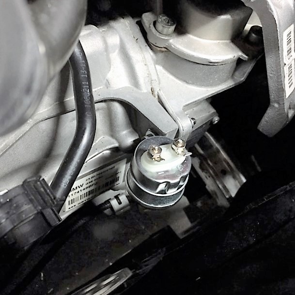
Installing the bracket for the Gauge Sender
- Take the included Gauge Sender Bracket and install it onto the tab hole on the transmission housing. Order of parts assembly is; Cap Head Screw>Small Washer>Sender Bracket>Transmission Tab>Large Washer>Locknut. See image for orientation.
You're now ready to connect the copper hose to the approriate sender unit. Once complete, reverse the processes from the 'Accessing The Sensor' section. Be sure to verify that all lines are clipped back in, all wiring is snugged back down into their fittings, your revervoir bracket is bolted down tightly and the reservoir attached with circlips fully seated. Remember to remove all four towels from the head and insure that all square O-rings on the intake manifold are seated correctly before bolting it back down. Finally, bolt the intake manifold snugly, verifying all five bolts.
Congratulations… your gauge sender adapter install is complete. You're now ready to install your gauge and wire it up!