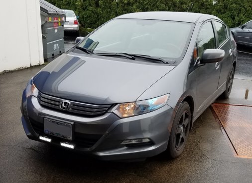
THANK YOU for purchasing the 2010 to 2014 Honda Insight Aux Light Kit from CravenSpeed. This product is made from the highest grade materials, and is guaranteed to be free from defects.
Parts Included:
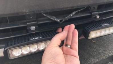
- 1 pr Auxiliary Lights (Flood Pattern)
- 1x Light Wiring Harness
- 1x Main Mounting Bracket
- 2 ea U-shaped Light Brackets
- 2 ea M8 x 14mm Hex Head Screws
- 2 ea M6 x 20mm Socket Cap Screws
- 4 ea M5 x 12mm Socket Cap Screws
- 2 ea M8 Nuts
- 2 ea M5 Locknuts
- 2 ea Split Washers
- 2 ea Flat Washers
- 4 ea Male Quick Disconnect Terminals 22-18 AWG
- 1x 4mm Hex Key
- 5 ea Zipties
Tools Required:
- Ratchet Wrench w/ 10mm Socket
- 14mm Socket
- 5mm Hex Key
- Wire Terminal Crimper Tool
- Scratch Awl (or something similar to poke through the rubber firewall plug.)
- Trim Panel Removal Tool (a screwdriver will also work if careful)
- Utility Knife
Procedure
Assemble the Lights and Brackets
- To build the Aux light, sub-assemblies, spread out your components and set aside the following parts: main mounting bracket, (2) aux lights, (2) u-shaped light brackets, (2) M8 x 14mm hex head screws, (2) split washers, (2) M8 nuts, (4) M5 x 12mm cap head screws, (4) M5 locknuts, and (4) male quick disconnect terminals.
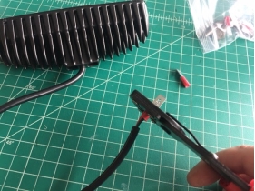
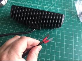
- Utilizing the wire terminal crimper tool, attach the male quick disconnect terminals to the ends of the aux light wire leads.
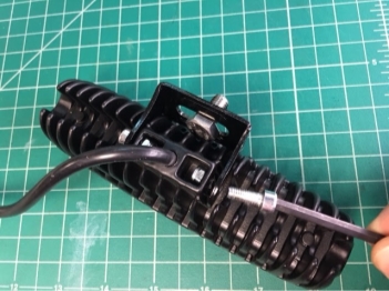
- Place the M8 x 14mm screw through the u-shaped light bracket before attaching it to the light housing. Set an M5 locknut into the recesses on either side of the light housing where the power cable exits. Utilizing the included 4mm hex key, set the bracket (w/ M8 screw) into place and tighten the two M5 cap screws.
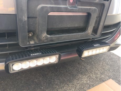
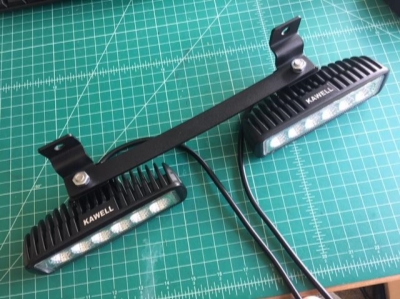
- Attach the individual fog light assemblies to the light bracket using the M8 nut and split washer. (See image for proper orientation). The lights mount onto the underside of the horizontal crossbar surface, not onto the vertical mounting tabs. There is some room for adjustability, but for these instructions, just center everything up and tighten. Ensure the lights are at the same level and spread.
Install the Light Wiring Harness
- The wiring harness includes an on/off switch that will be mounted inside the cabin of the vehicle. To accommodate this switch, we need to install the wiring harness through the firewall inside the engine compartment. There is a rubber plug centrally located on the firewall behind the airbox that some factory wiring runs through, however, to access this plug you’ll need to remove the factory airbox up to the throttle body.
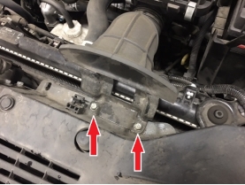
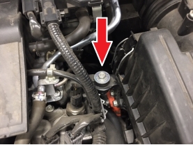
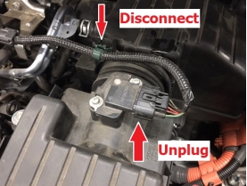
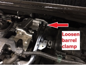
- The thought of removing a few components of your engine may sound a little intimidating at first, but rest assured.. the process is simple and painless. You may get a little dirty though, so dress accordingly. The following images show the fasteners that need removal. Take your time and remember where things were removed and need to be reinstalled.
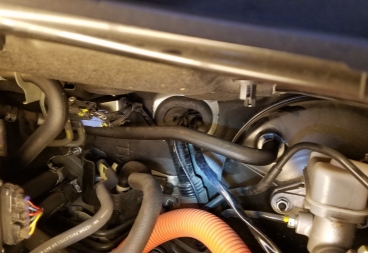
- Once you have all the necessary fasteners and plugs removed, lift out the airbox and you should be able to access the rubber firewall plug.
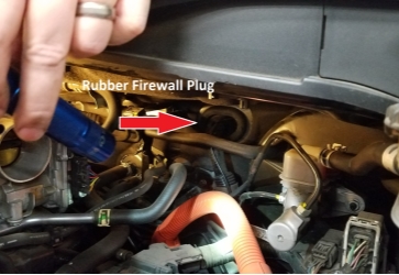
- Once you have the rubber firewall plug in sight, you will notice a recessed area just to the right of where the factory wires go through. Use your scratch awl (or similar tool) and poke a hole through the rubber plug in this area. Take care that you’re not damaging anything on the opposite side. NOTE: In the image below, the light wires have already been installed through the firewall plug.
- NOTE: This next step is much easier with the help of an assistant. Take the auxiliary light wiring harness, unwind and spread it out then unplug the on/off switch lead from it. From the engine compartment side, push the wiring harness side of this plug through the hole you created earlier. The rubber is quite stretchy, but a little WD40 or silicone spray will greatly help with getting the plug and wiring through more easily. Have your assistant lie on their back inside the vehicle, looking up behind the dash with a flashlight to watch for the plug emerging from the firewall. Once they see it, have them pull enough of the wiring through so that when the on/off switch is reconnected, it will reach the dash panel just below and to the left of the steering wheel. As the wiring is being pulled through, be mindful of the excess wiring in the engine compartment and do not allow it to get hung up on the various engine components or become too taunt. Utilize a few of the included zipties to hold the wires out of the way from hot or moving engine components. Reconnect the on/off switch lead back onto the light wiring harness.
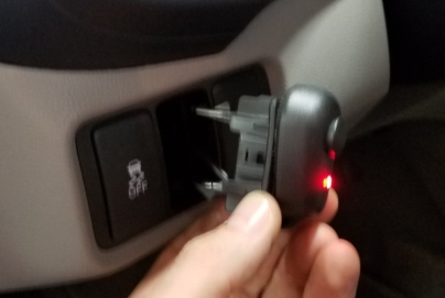
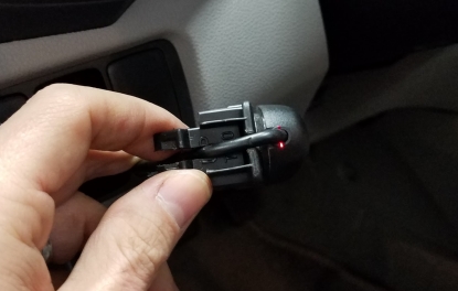
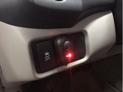
- In this lower left area of the dashboard, there is a small access panel located on the underside of the dash that needs to be opened. Having this panel removed will not only assist in feeding the on/off switch wiring to this area of the dash, but you should also be able push one of the small, removable panels (approx 1x2) from the backside. Feed your switch wiring through the small panel opening and affix the switch housing to the small panel via double-sided tape on the back of the switch.
- Take your utility knife and make a small circular cut on the bottom edge of the small panel so the on/off switch wire can pass through with the small panel reinstalled. If necessary, use a ziptie or two to affix the switch wiring under the dash to keep it out of the way from the vehicle’s controls.
- Back to the engine compartment, we’ll be finishing the installation of the light wiring harness. The wiring harness does include it’s own installation instruction diagram, but we’ll cover some specifics about installing it into the Honda Insight. So, we’ve got the wiring going through the firewall plug, but what to do with the rest of the stuff? Let’s again make sure the wiring harness is spread out so we can assess the various components and the order in which we will proceed.
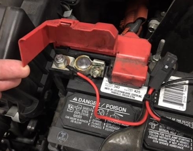
- NOTE: At this point in the installation, it is strongly recommended that you disconnect the negative lead on the battery to prevent any accidents while working with the electrical system. Loosen and completely remove the negative clamp from the (-) battery terminal. Assure that it is completely isolated and cannot accidentally touch and energize the system while you’re working.
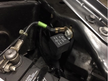
- There is a battery grounding bolt located on the side of the engine compartment, just to the right of the battery. Remove this bolt and place it through the mounting tab of the relay with the short black ground wire (from the relay) attached onto it. Reattach this entire assembly back onto the side of the engine compartment with the bolt you removed. (See image for orientation) Note: The negative battery terminal is reattached in the image below, however, it should remain disconnected for the duration of the wiring installation.
- Attach the red battery power lead (from the inline fuse) to the accessory nut on the positive (+) battery terminal.
- Finally, run the two aux light leads down through the front fascia of the vehicle, just in front of the radiator. You want the wires to exit out the front of the vehicle through the top slot of the radiator intake vent, just behind where the license plate mounts. Affix any loose wires with the included zipties so they do not rest against the hot radiator.
Mounting the Aux Light Assembly
- The CravenSpeed Aux Light Kit will mount to the lower two screws holding the factory plastic license plate mount to the front bumper. Utilizing a 10mm socket, remove the bumper mounted license plate holder. You will need to remove the license plate to access these two screws.
- Place the light bracket assembly mounting tabs behind the license plate holder and utilizing the included M6 cap head screws and washers, bolt the light assembly along with the license plate holder back onto the front bumper with a 5mm hex key. If you find that there is some interference with the fog light screws/nuts hitting the underside of the license plate frame, you may need to clearance the plastic frame with a rotary tool and grinding attachment.
- Make your connections of the wiring leads to the aux lights by matching the polarity of the wires. Red to red, black to black. We recommend wrapping the terminals with electricians tape as an added precaution against the elements. Tuck any excess wiring up behind the license plate holder and reattach your license plate. Reconnect the negative battery clamp onto the negative (-) battery terminal and test out the lights by activating the on/off switch inside the vehicle. If the lights do not illuminate, check all of your connections and try again.
- Once you have functional lights, reinstall the airbox within the engine compartment then check the adjustment of the beam patterns against a wall when it’s dark outside. Adjust them so they do not impair the visibility of oncoming traffic and the beam spread is to your liking.