
Durability Testing Our GR86 Short Shifter - Part 1
Posted by Logan on 28th Feb 2024
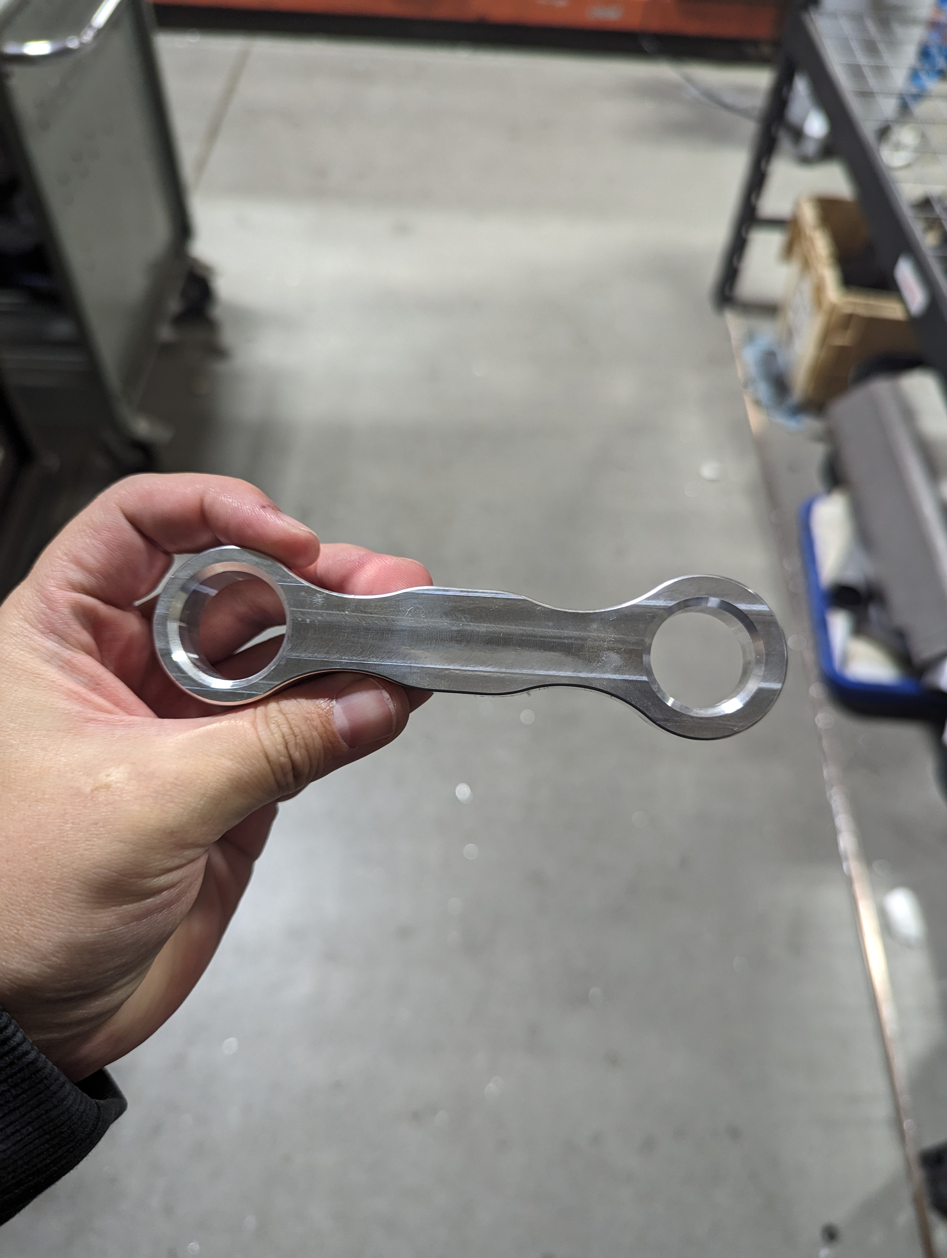
Welcome to part 1 of a three part blog series where we will take a deep dive into our strenuous testing process of our GR86 Short Shifter. Spoiler alert, the shifter passed with flying colors and is available now!
When it came to designing our GR86 shifter we really wanted to make sure we had a bulletproof product. You can do all of the analysis you want but nothing will ever beat real world testing. The trouble is, putting the kind of mileage on our shifter that we expect it to be able to withstand would take a very, very, long time.
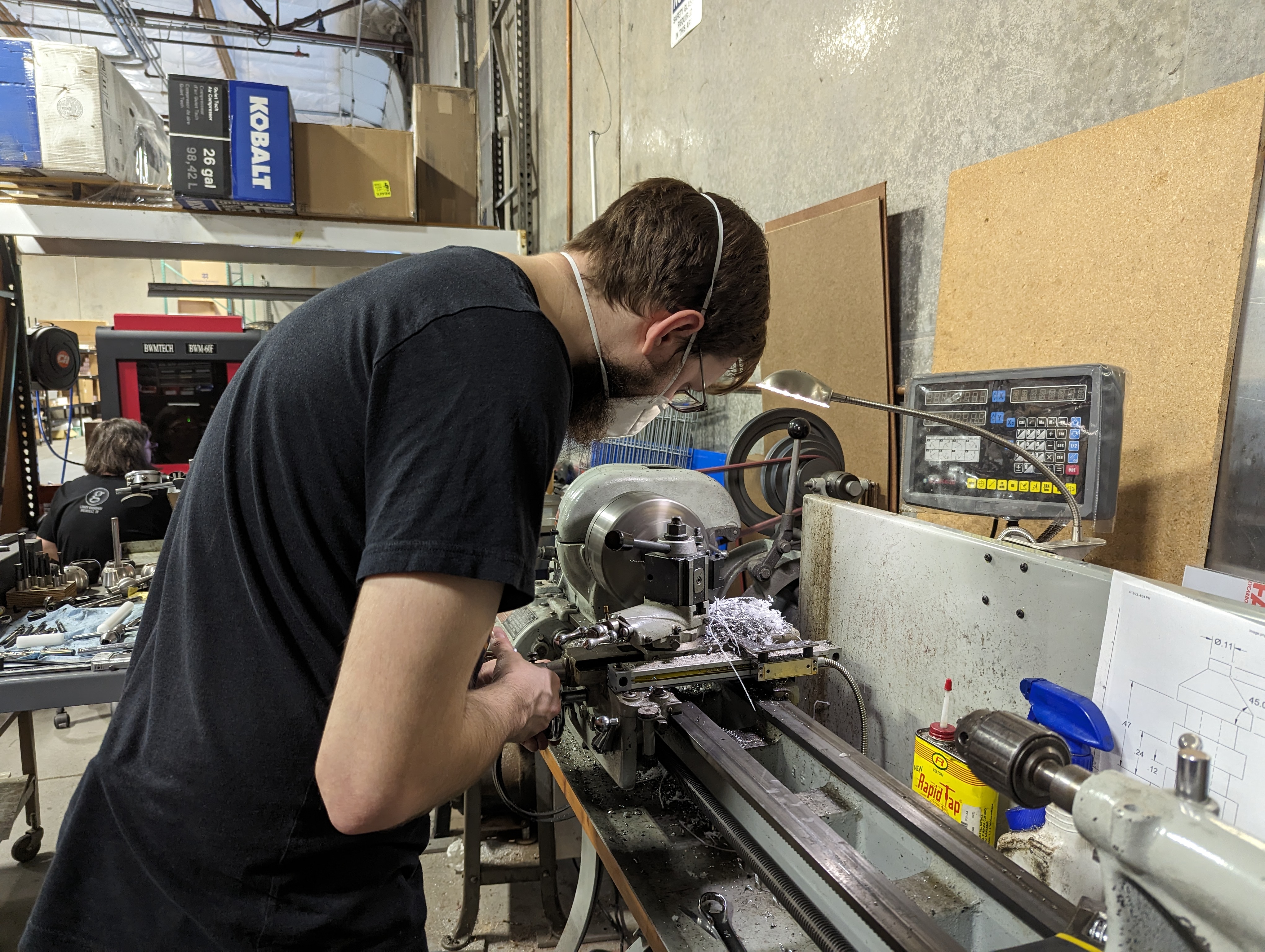
One Monday afternoon, Tristan brought us (Jacob, Steve, and I) the idea to make some kind of machine that could simulate a full lifetime of shifting in a matter of days. Being that this shifter was in stock and ready to ship, we really wanted to have the machine built and testing complete as soon as possible. We also wanted to spend as little as possible to get this going as we have an abundance of hardware/materials we could use in the shop. We generously set our goal to be complete within 1 month. We had the machine running within 7 days, and finished the first round of testing on the 16th day! But, as you may be able to tell, there’s a whole lot more to this story.
After our brainstorming session that Monday, I came into the office the next morning highly motivated to get the machine knocked out as fast as I could. We would need to design a machine that could stand up to 10 years of shifting. We gave that a rough estimate of 1,000,000 shifts! The goal for the day was to get the majority of the machine designed so that we could order all of the materials we needed that day to be delivered the next day. With Steve and Jacob handling some vital operational jobs, I took the reins on the general concept and talked the finer details through with them. It all started with some sketches.
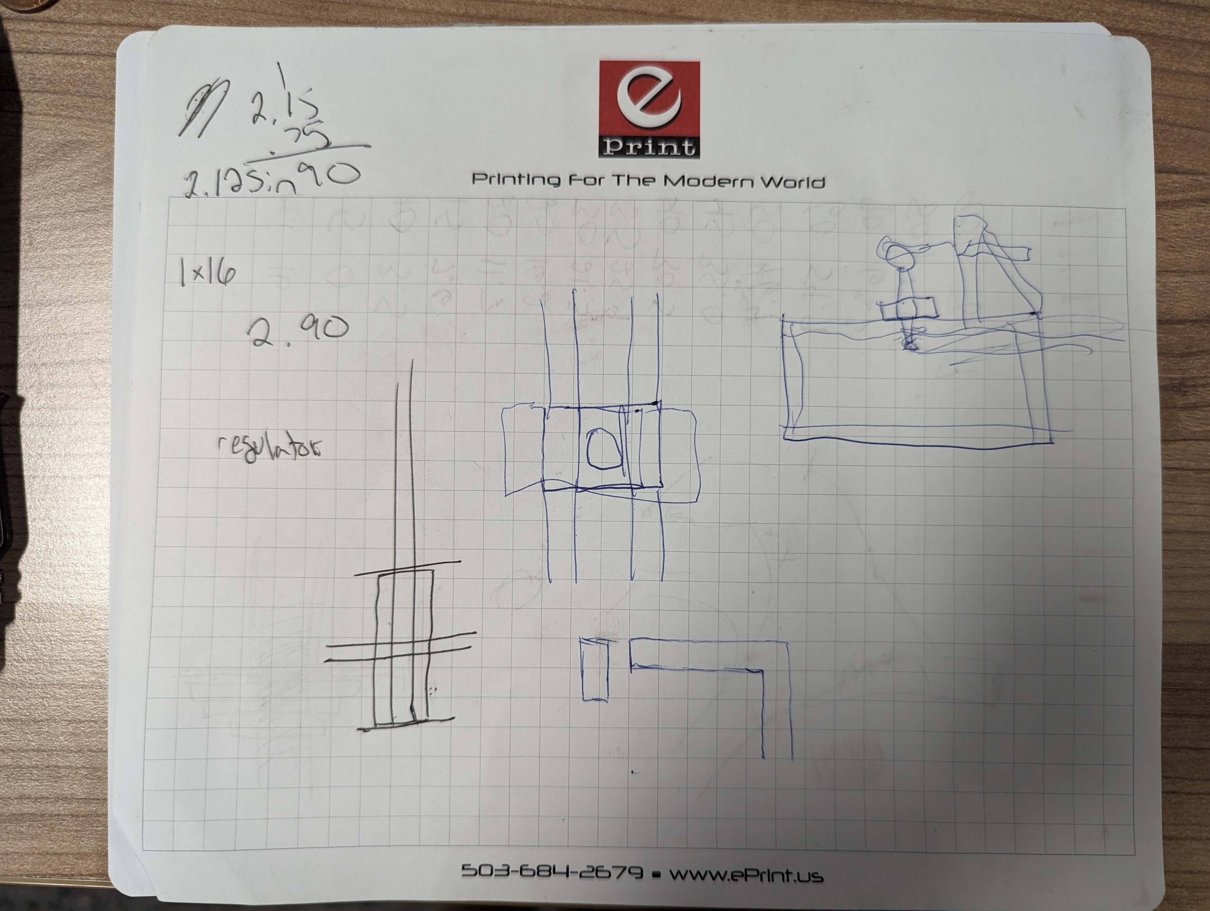 I should probably blur the part where I had to add .75 to 2.15 by hand, I was moving fast that day and the brain
just wouldn't give me the answer fast enough. I am not ashamed!
I should probably blur the part where I had to add .75 to 2.15 by hand, I was moving fast that day and the brain
just wouldn't give me the answer fast enough. I am not ashamed!
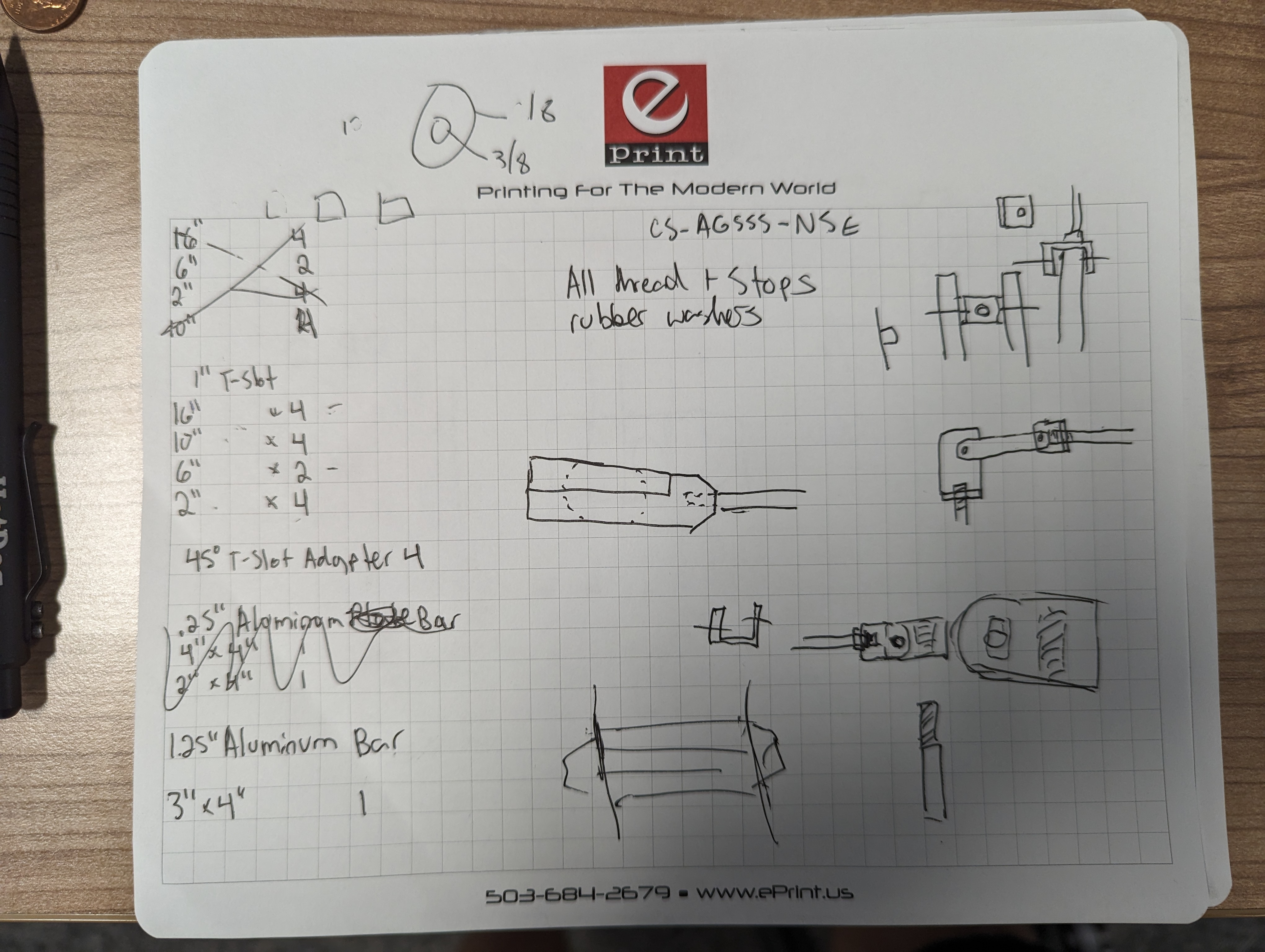
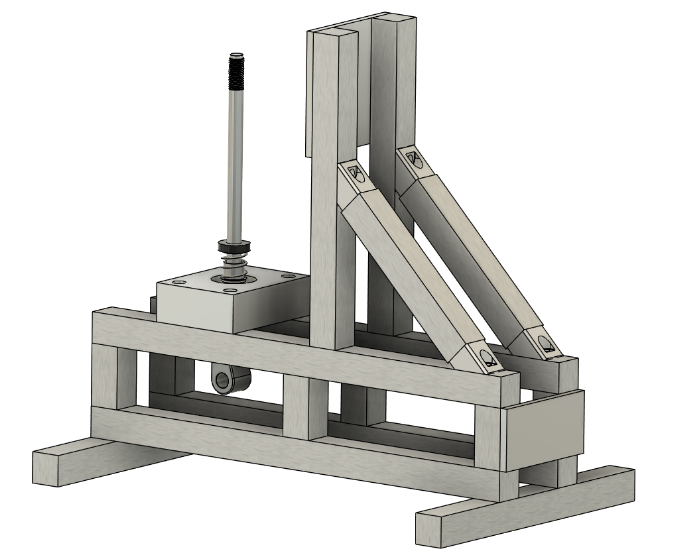
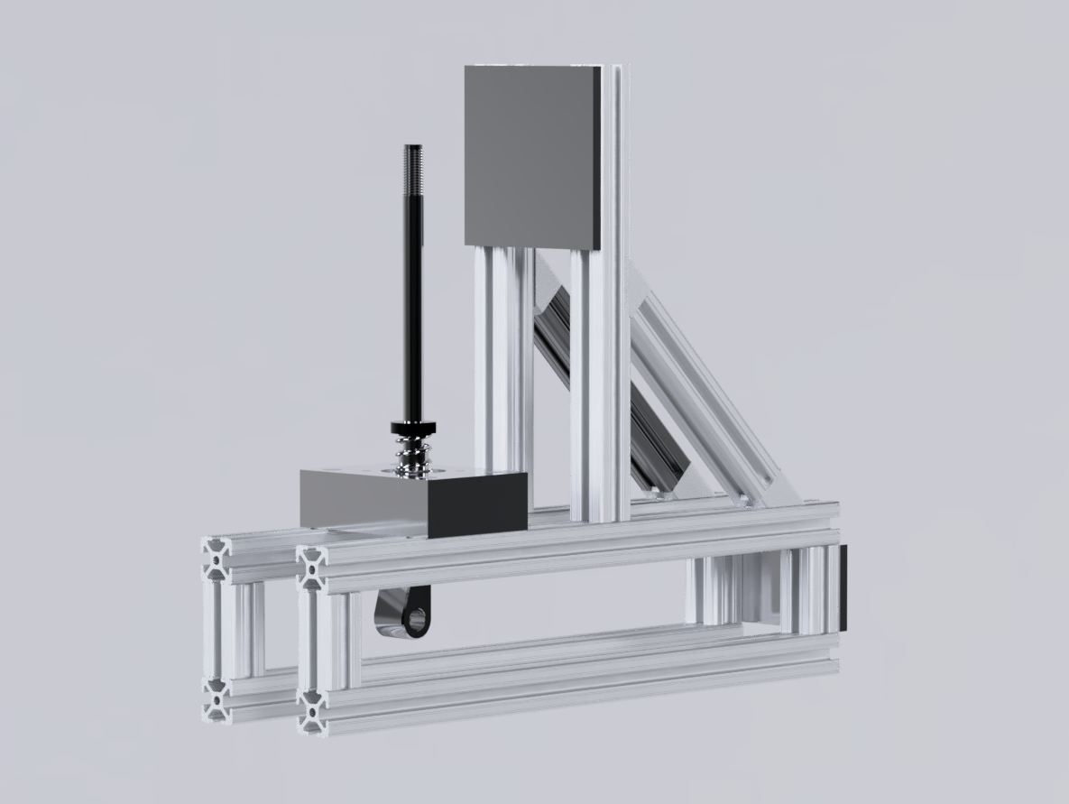
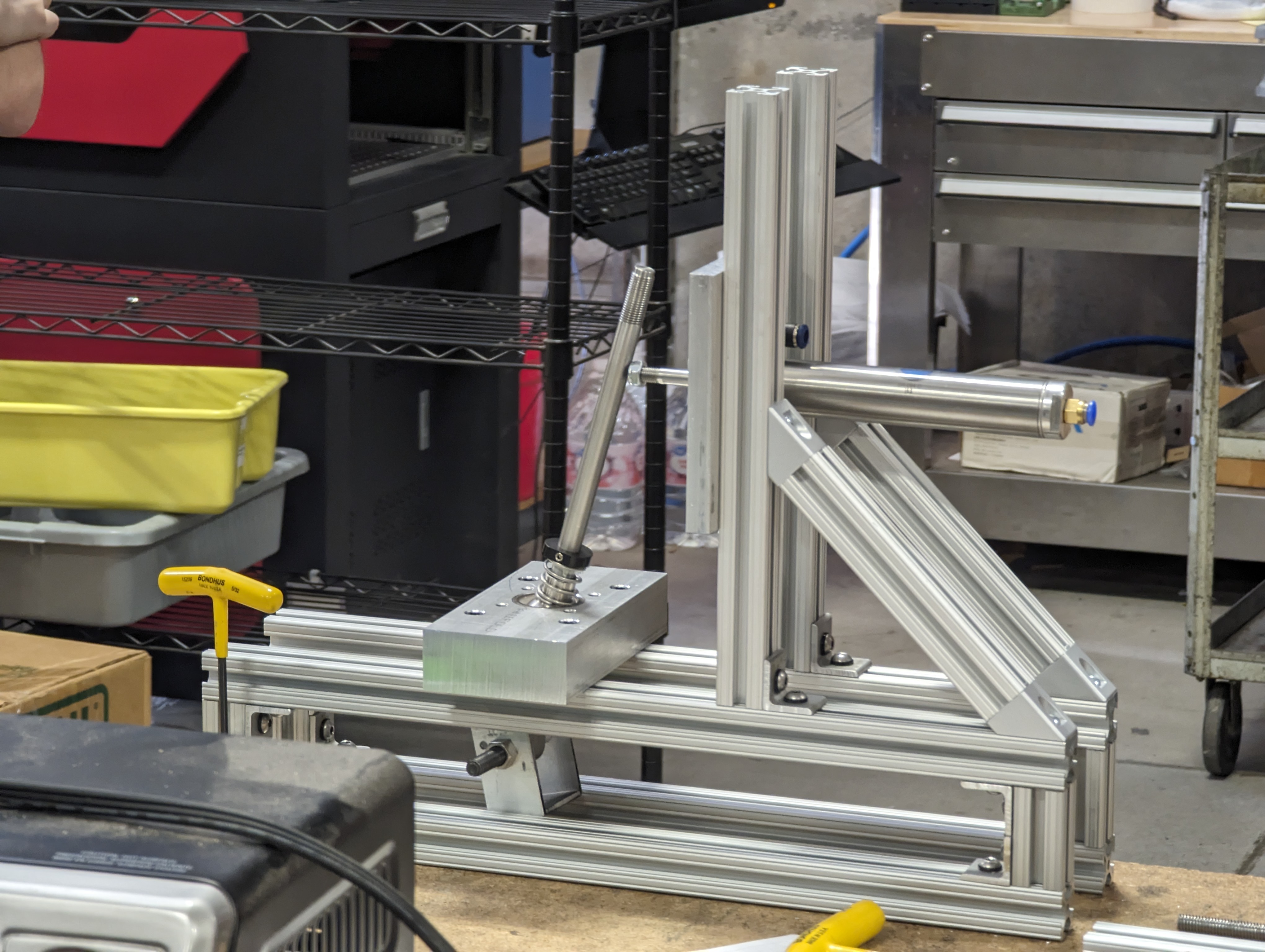
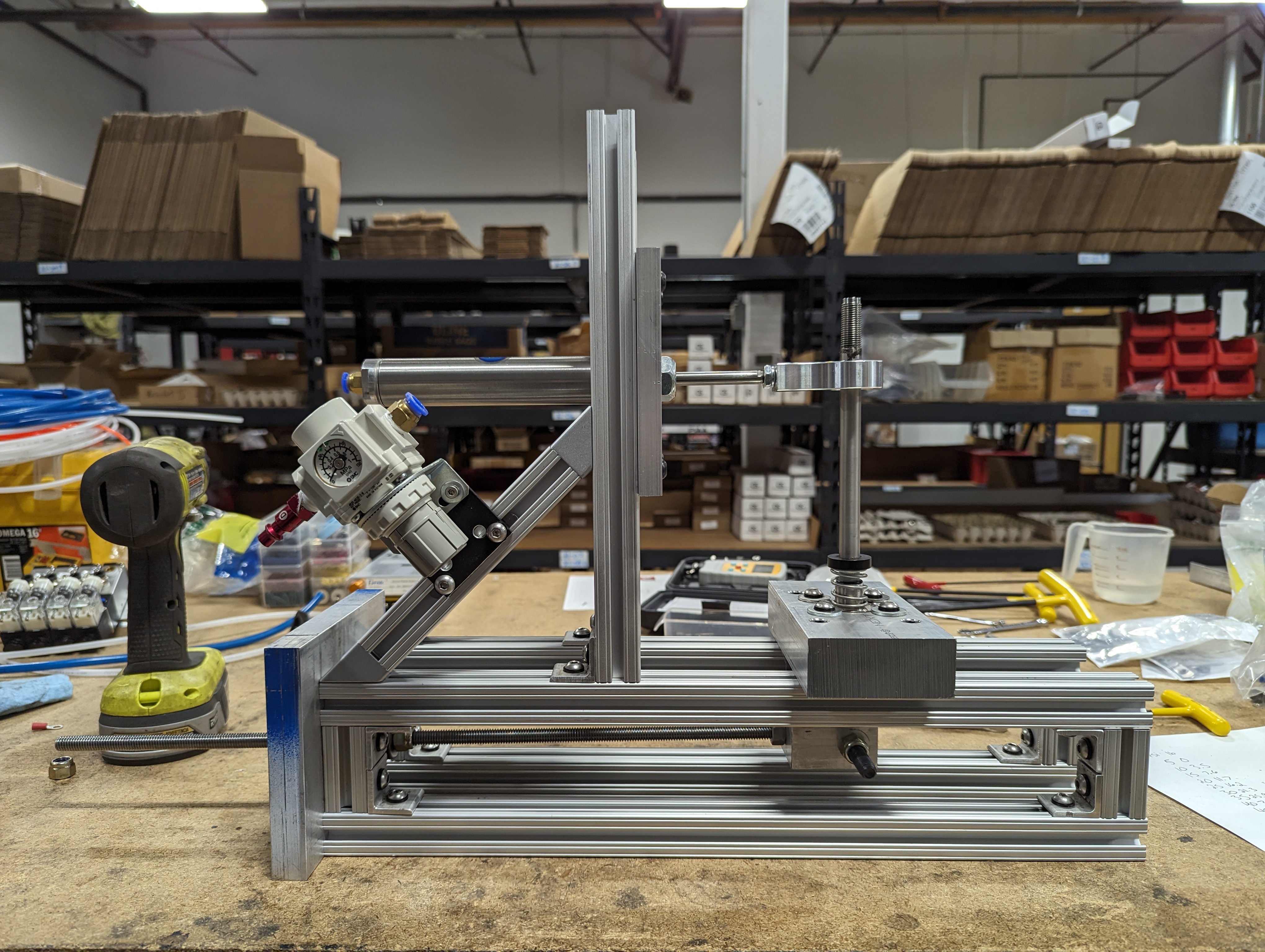
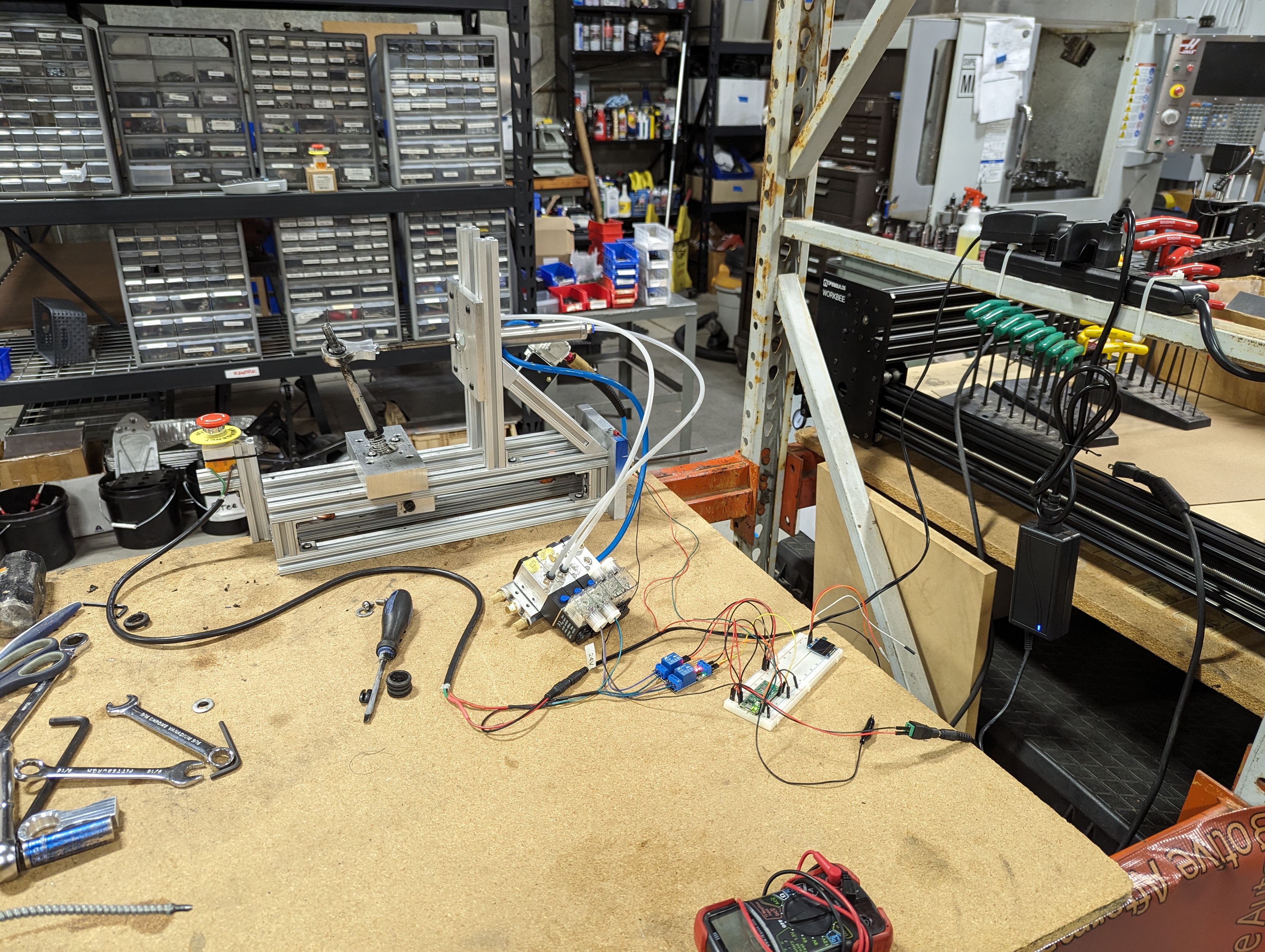
We came up with the plan to build a frame out of 1” aluminum t-slot framing. This would be more than strong enough to handle the forces that we were expecting to be involved. We had to come up with a way to mount the shifter into the frame. With the shifter mounted we could use an air cylinder to actuate or “shift” the shifter. We would need some kind of interface between the air piston and the shifter itself. Then we would need some kind of linkage with stops to limit the travel of the shifter so that it matched the throw of the GR86. With the general concept done I took to the CAD software and got it mocked up so we could begin to iron out the final details and make sure we had a plan for everything.
At this point we didn’t quite have everything set in stone, but this model was enough for us to place an order for any of the materials we thought we would need including the t-slot framing, some raw aluminum stock, and a little bit of hardware. The first order ran us about $277.
By the time I got into the office on Wednesday, the parts had already arrived!


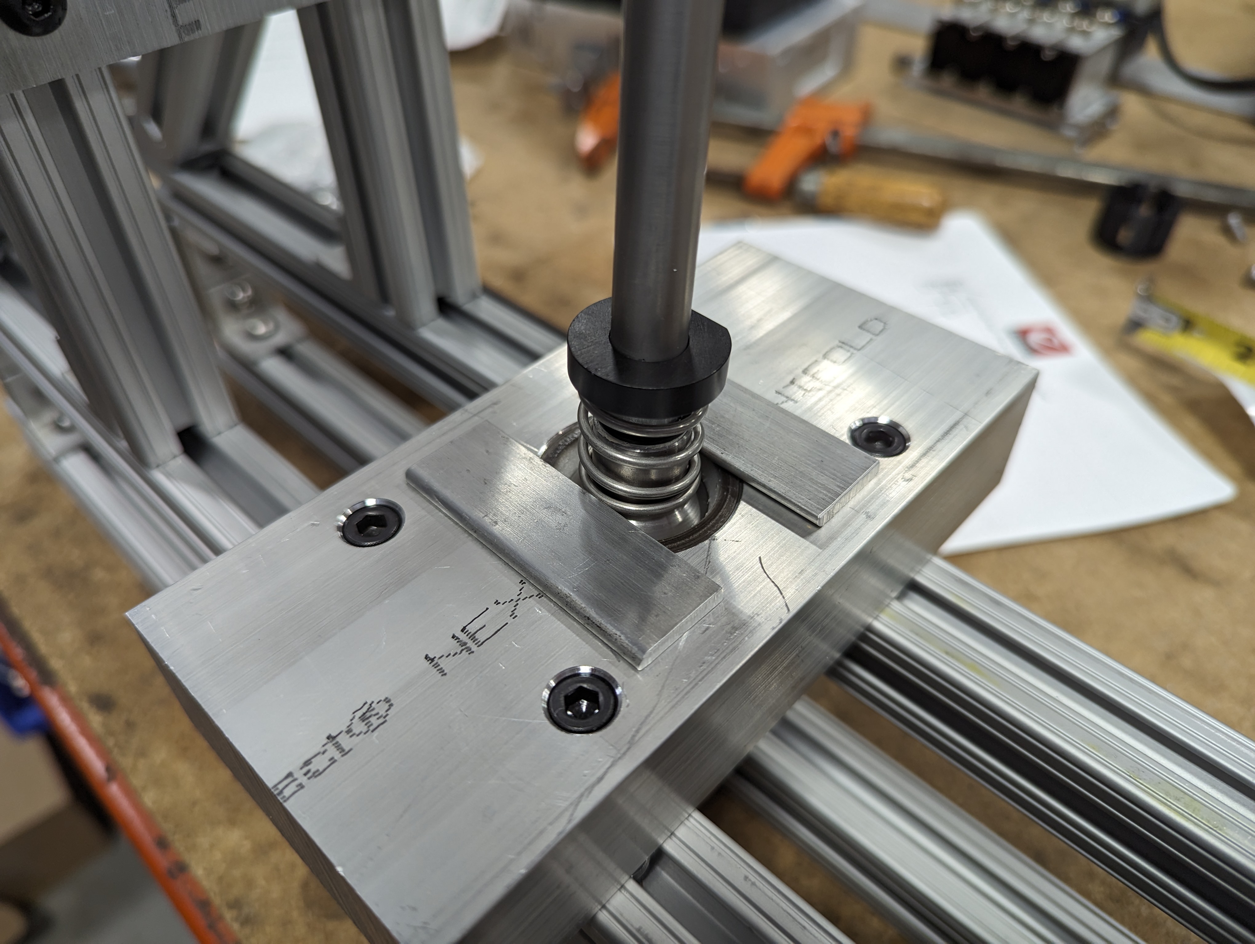
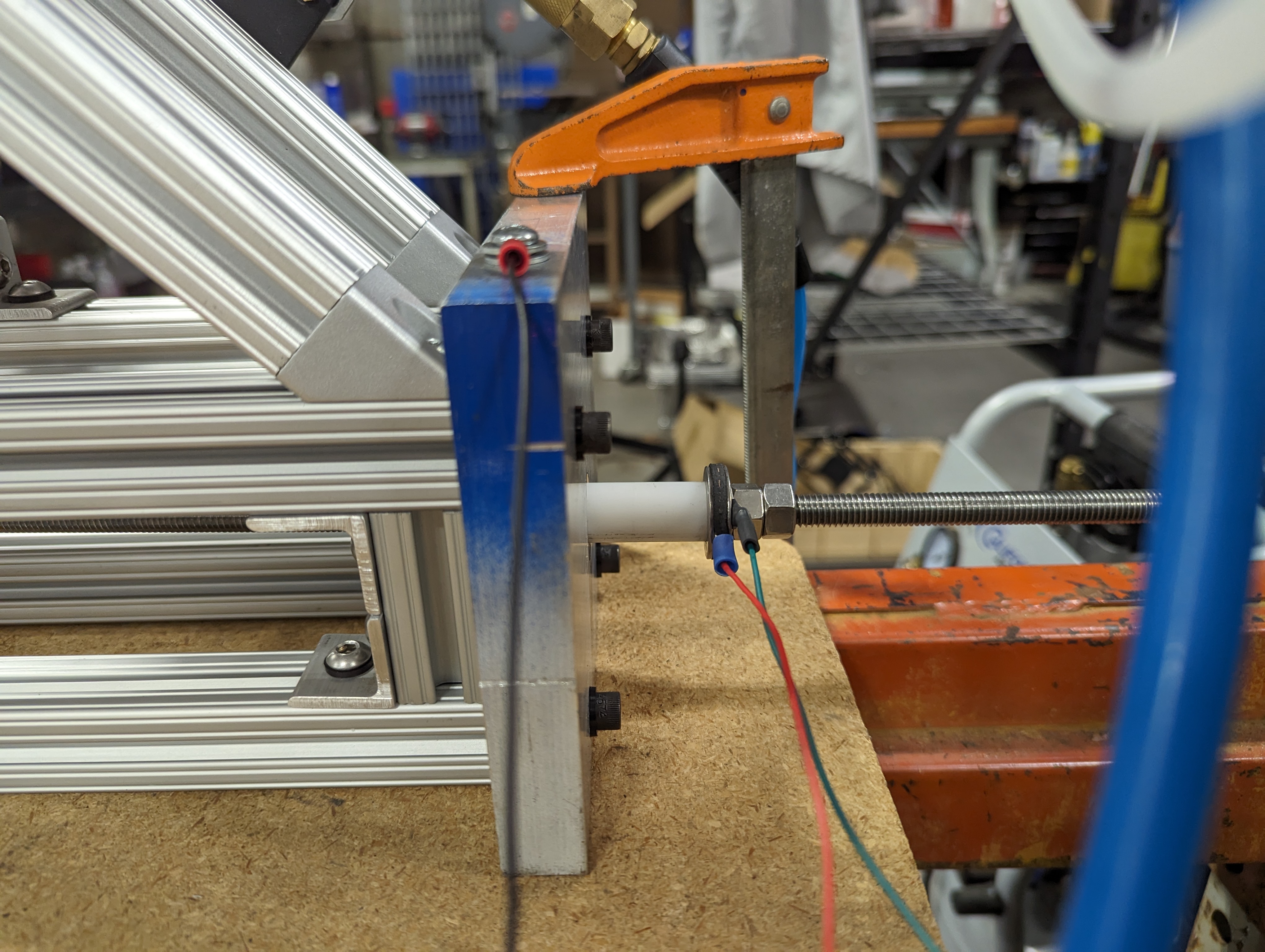
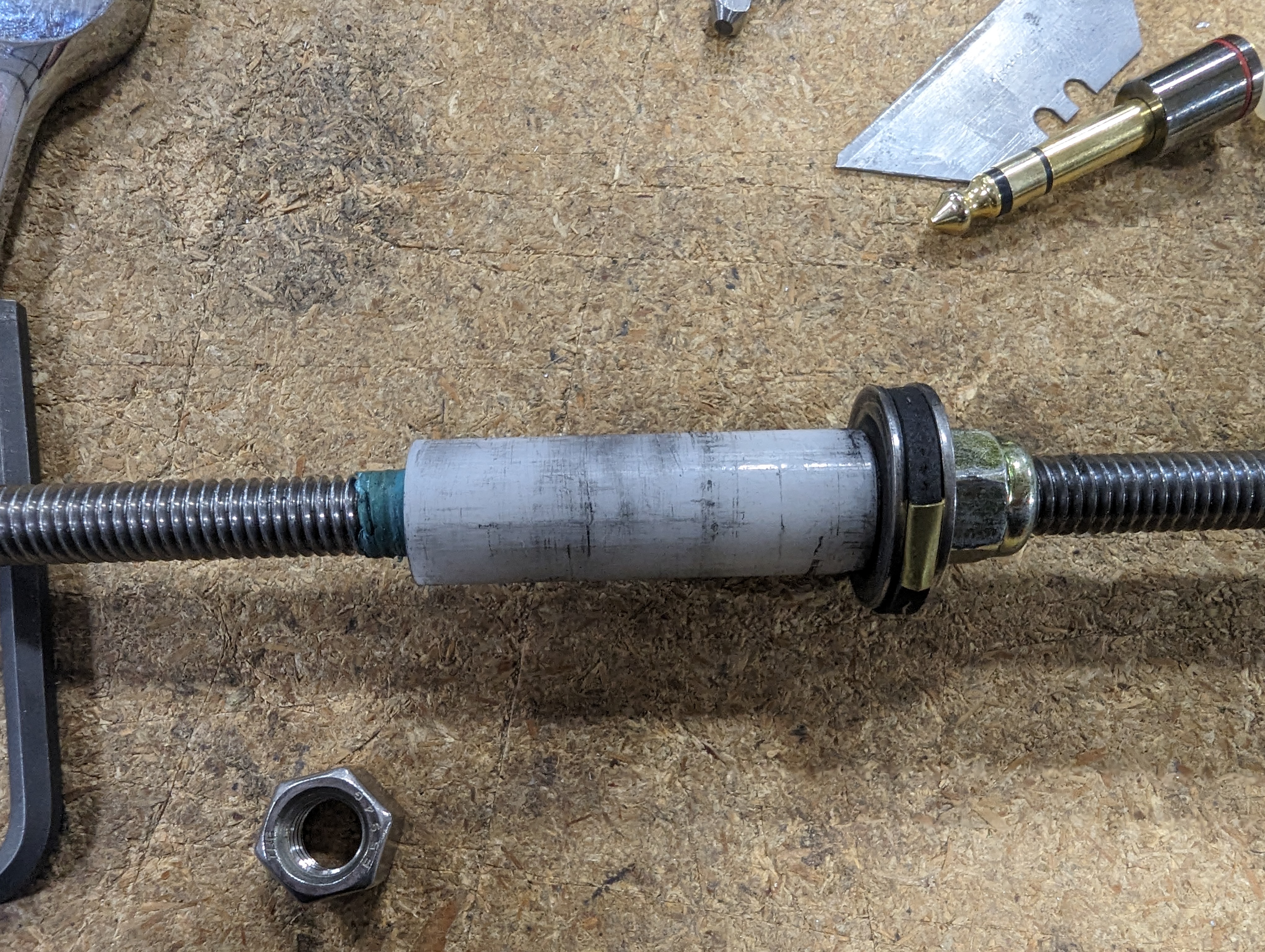
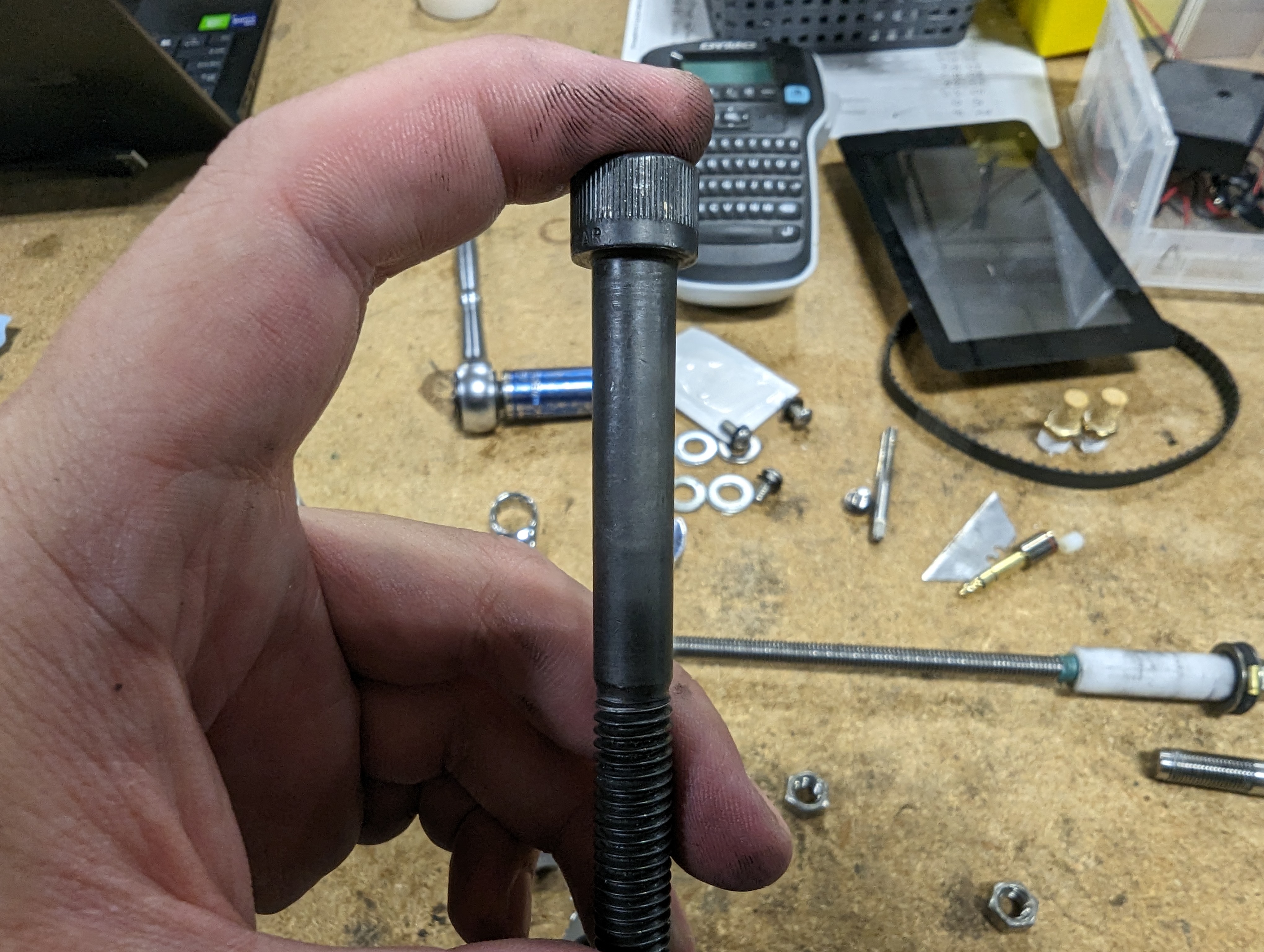
Right away I got to work mocking up the frame. With the framing I only had to make a few cuts to get the 2” vertical pieces I needed. In the photo below you can see the beginning of our plan for limiting the travel of our shifter. A piece of all thread would eventually be connected to the bottom end of the shifter. This would travel the length of the frame and pass through an aluminum plate. A white acetal bushing would allow the all-thread to ride smoothly in the hole while steel washers sandwiching rubber washers and held in place with nuts would provide the stops. Later we even came up with a clever way to use the steel washers as switches.
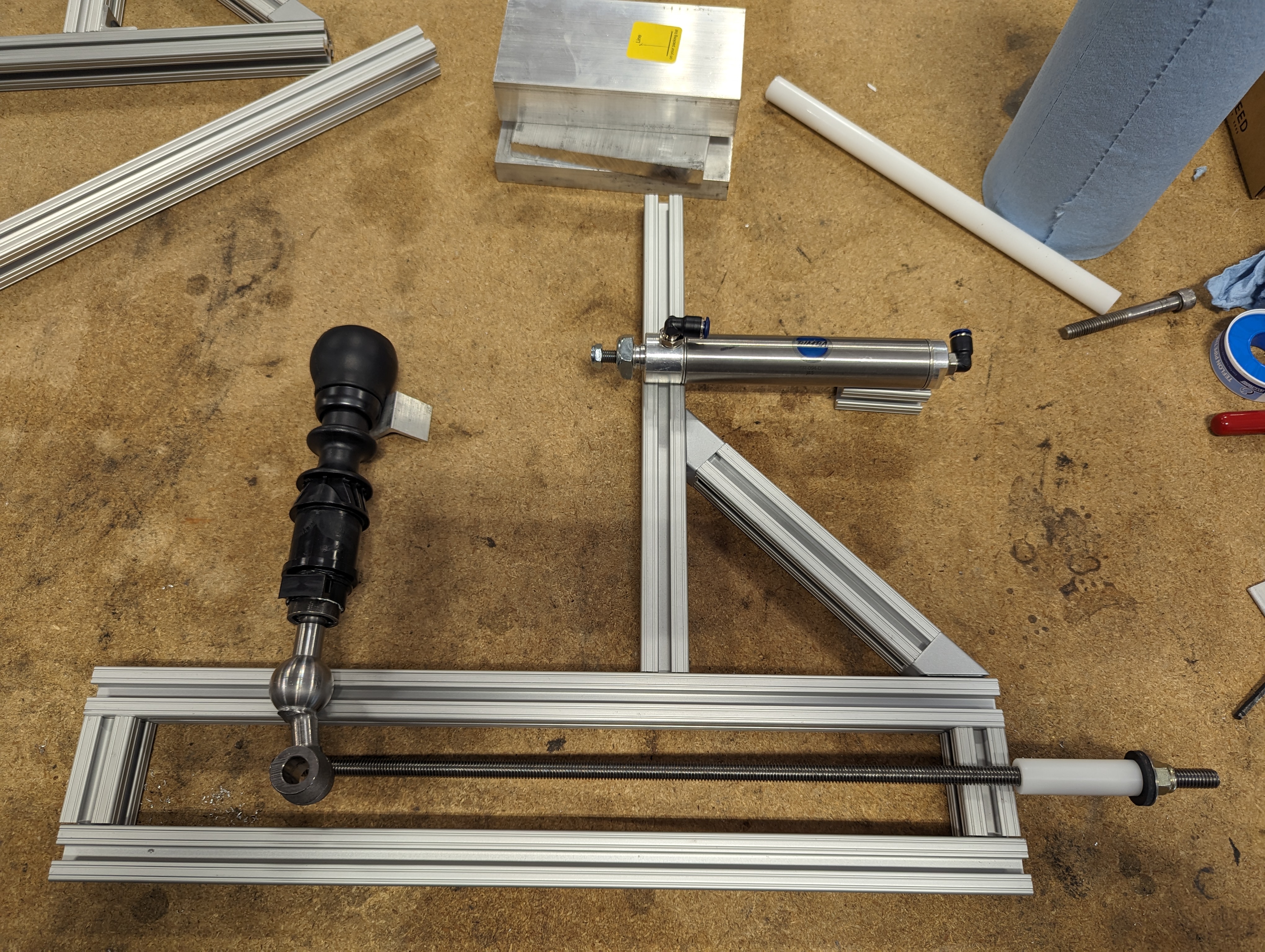
The brackets for attaching the framing were very expensive, but we had some 1” angle aluminum sitting in the scrap pile, so Steve made up a bunch of brackets for me to use.
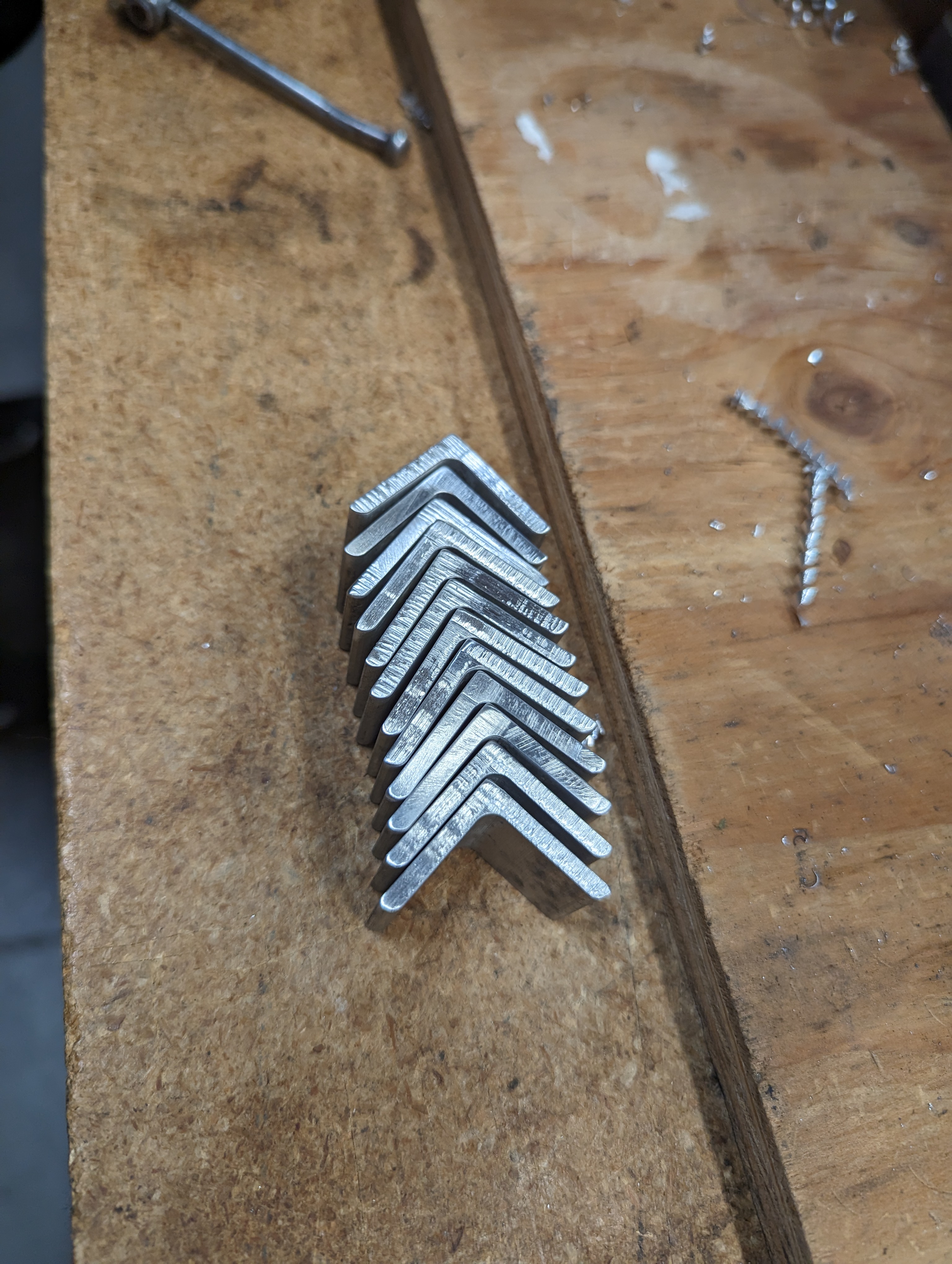
With the first set of 8 I was able to get each side of the machine assembled. This got a little tricky as my vertical pieces ended up being a little short of 2”, so there wasn’t enough room for 2 1” brackets. Not to mention the t-nuts were also interfering with each other. A session grinding down parts on the belt grinder took care of these issues.
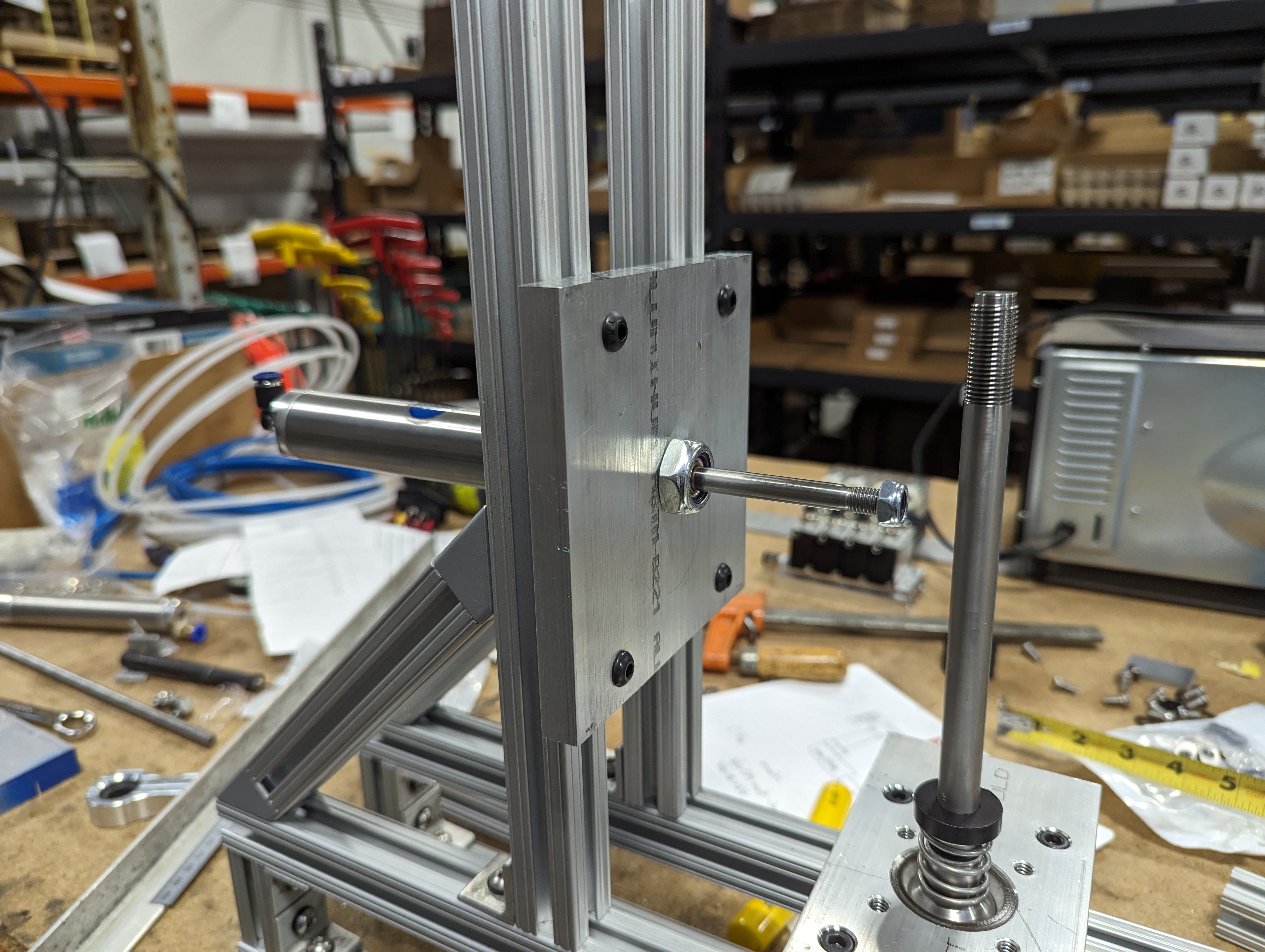
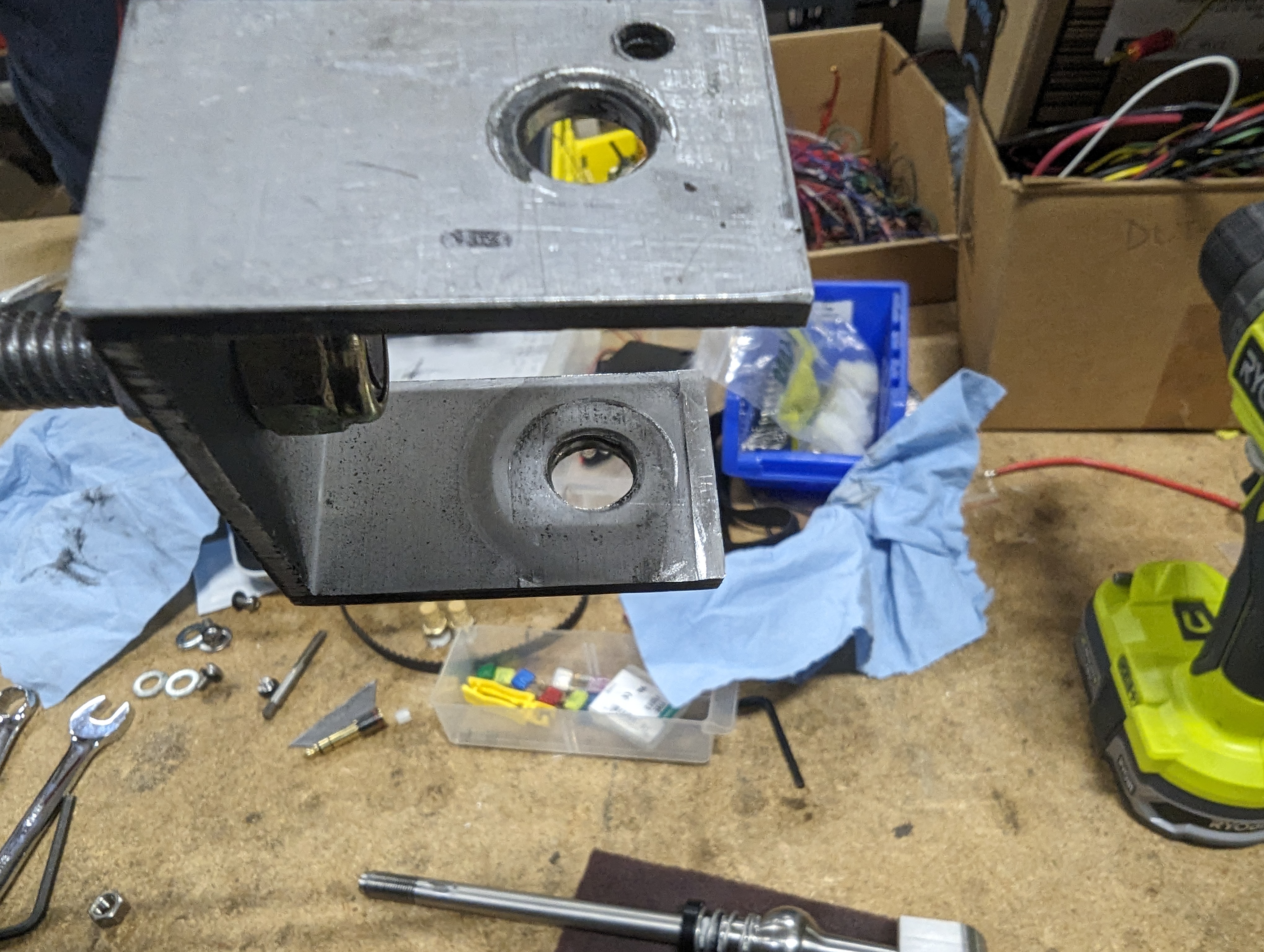
The two sides of the frame would be connected together by three aluminum plates. The first of which would mount the shifter, the second would hold the air cylinder, and the third was a structural plate that also gave the washer stops something to run into and ground out on later.
At this point we were going to start CNC machining some parts, so I finalized the CAD model and set everything to final dimensions.
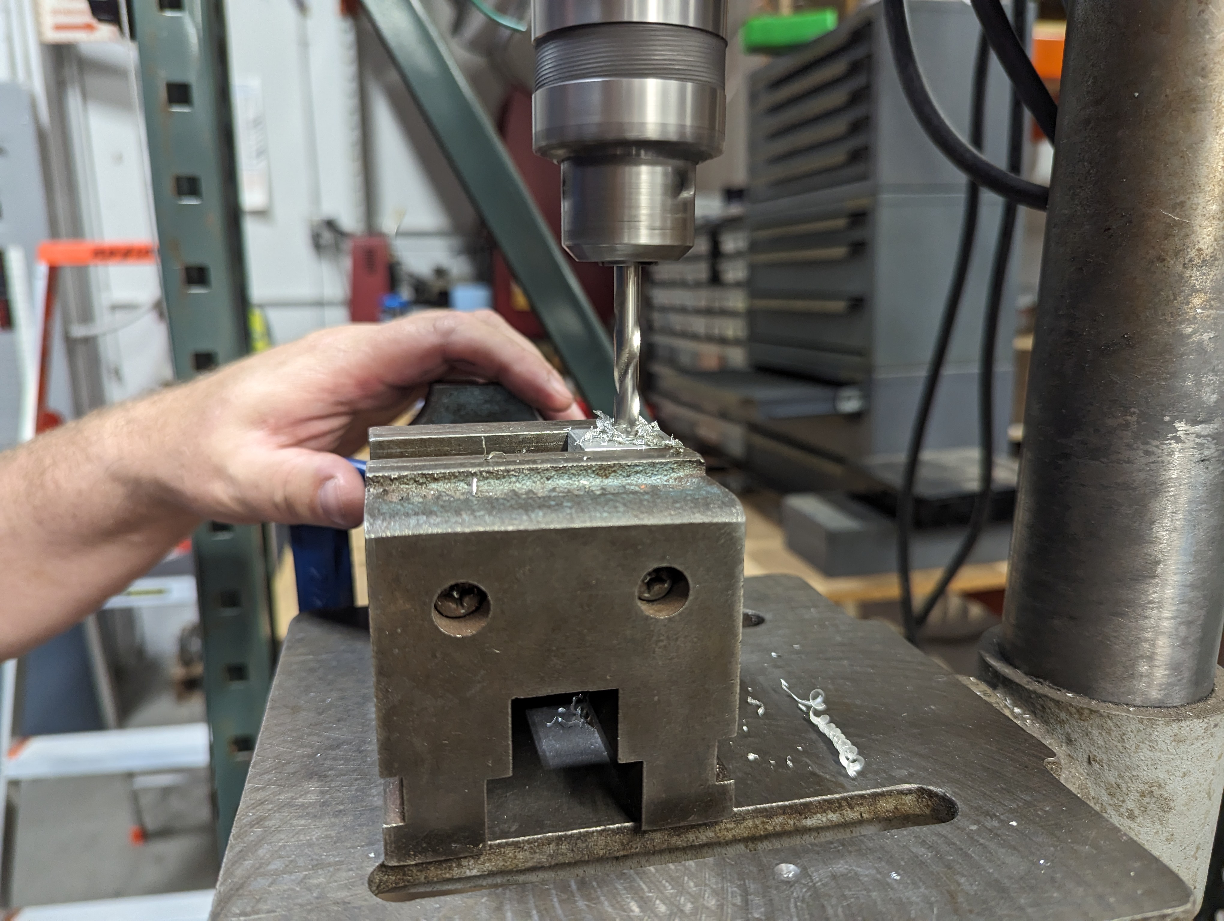
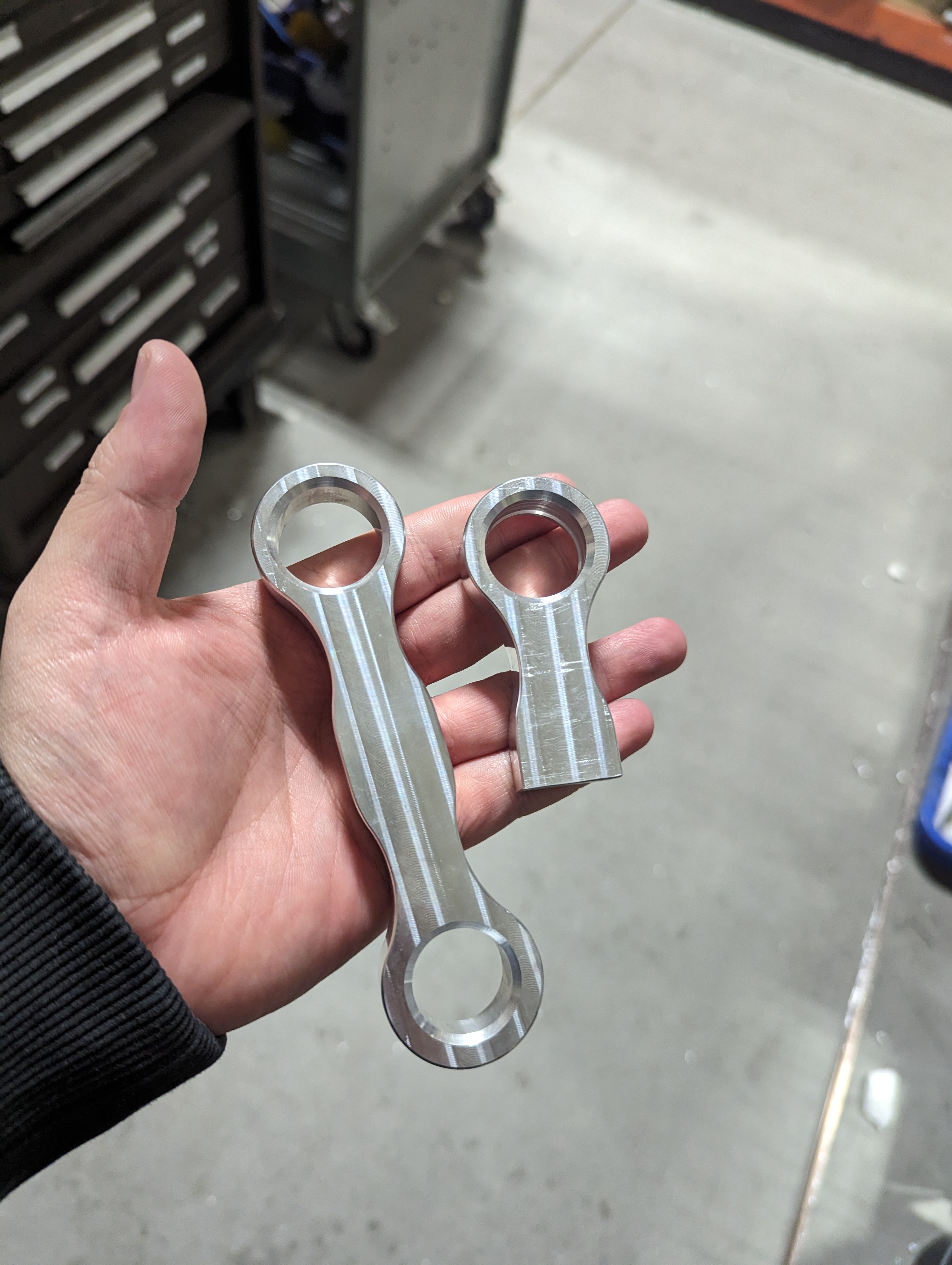
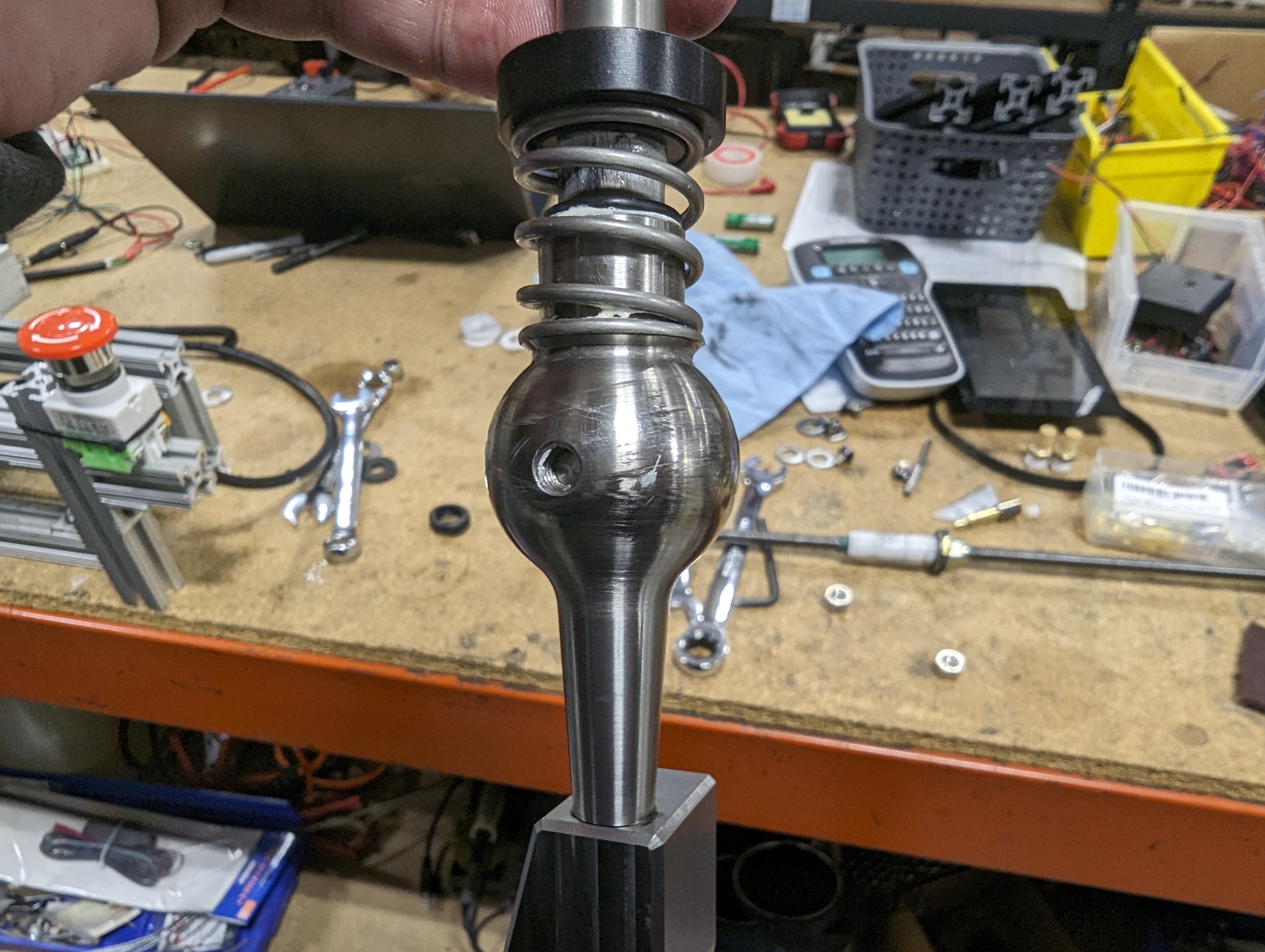
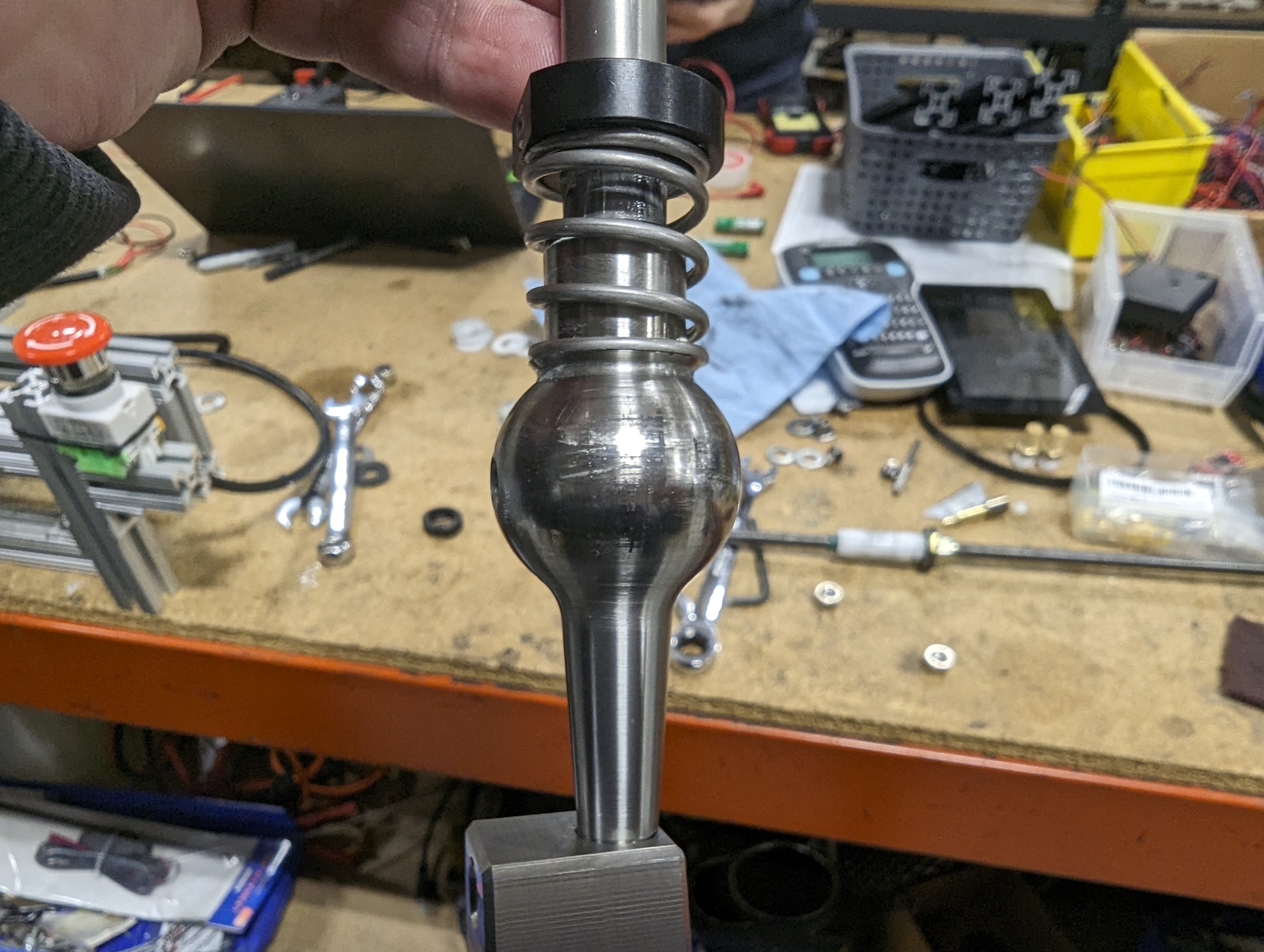
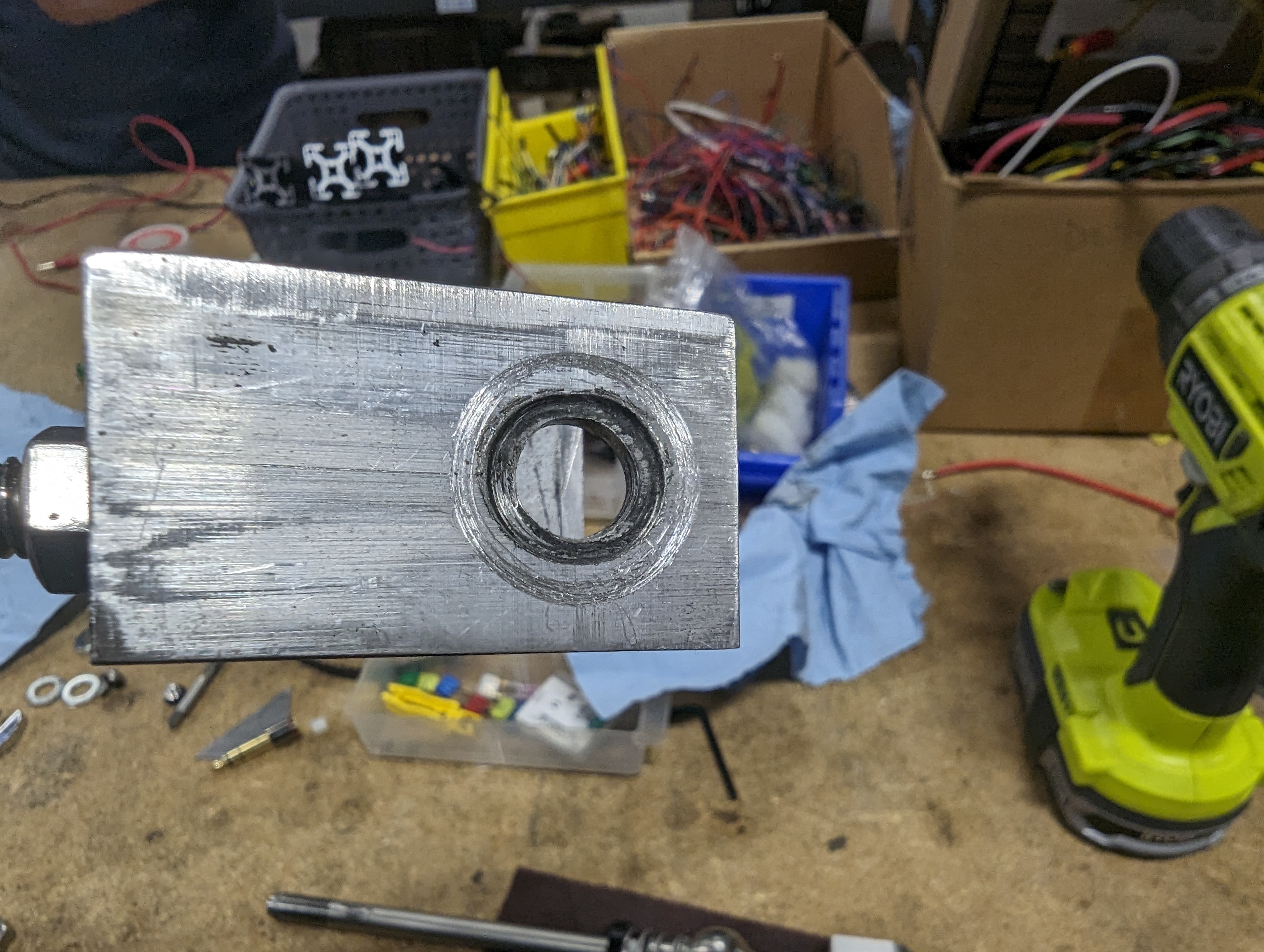
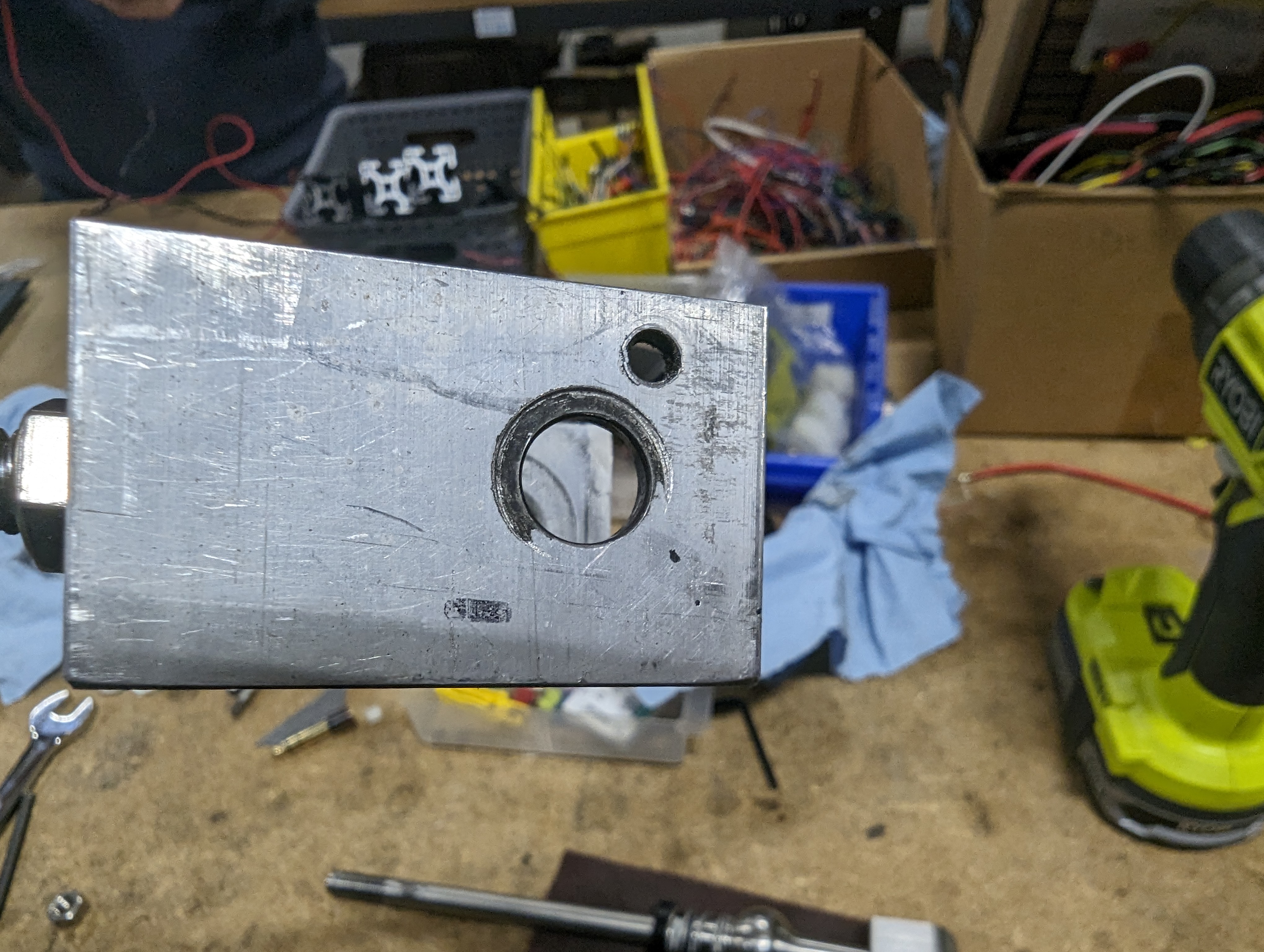
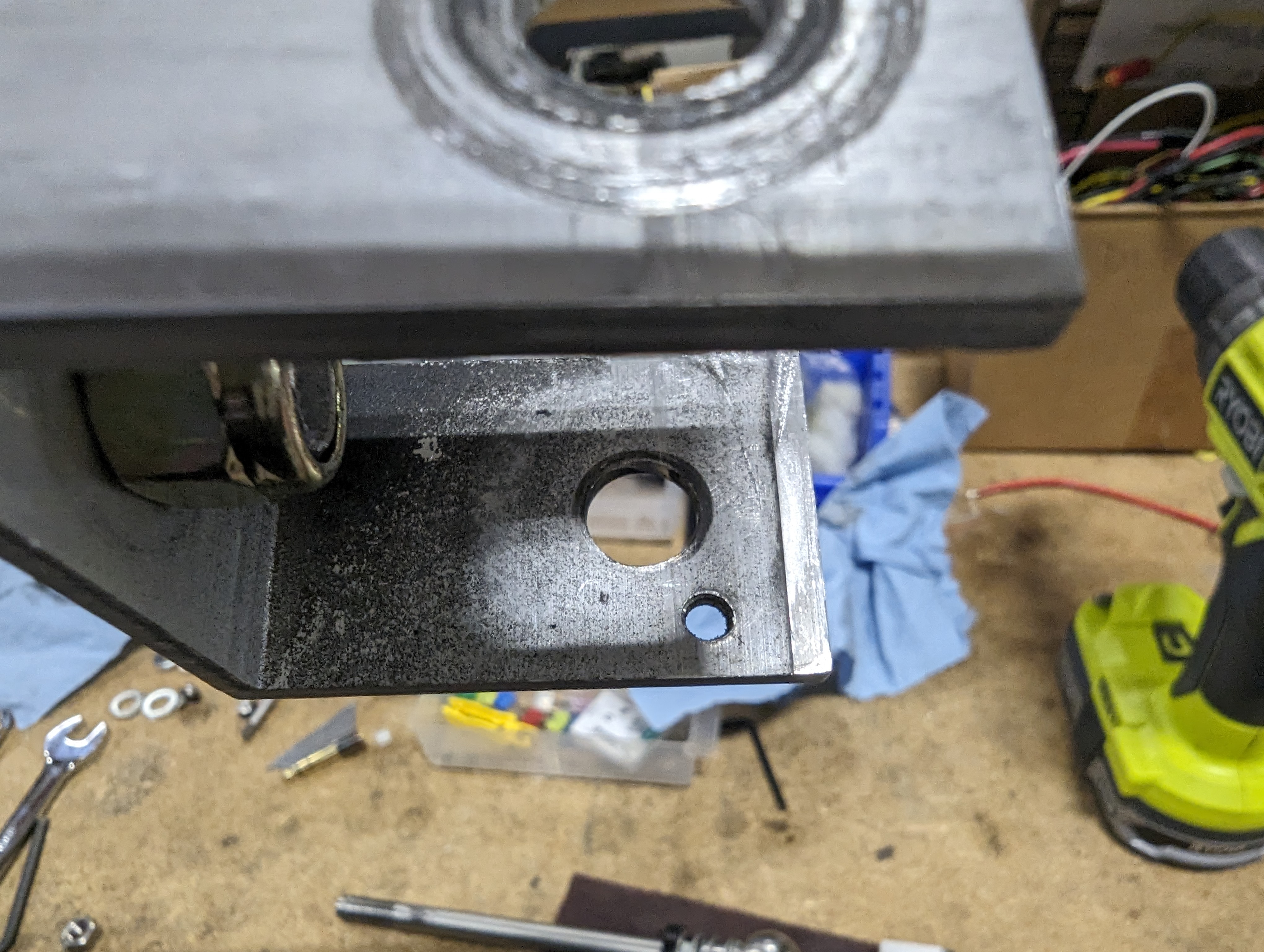
Jacob machined the shifter block first. This had one counterbored hole in the center where the nylon retaining clip would be installed. Four ¼-20 holes around that were created to allow us to attach something that would retain the retaining clip. Finally 4 more counterbored holes were made in the corners that would allow us to bolt this block to the frame.
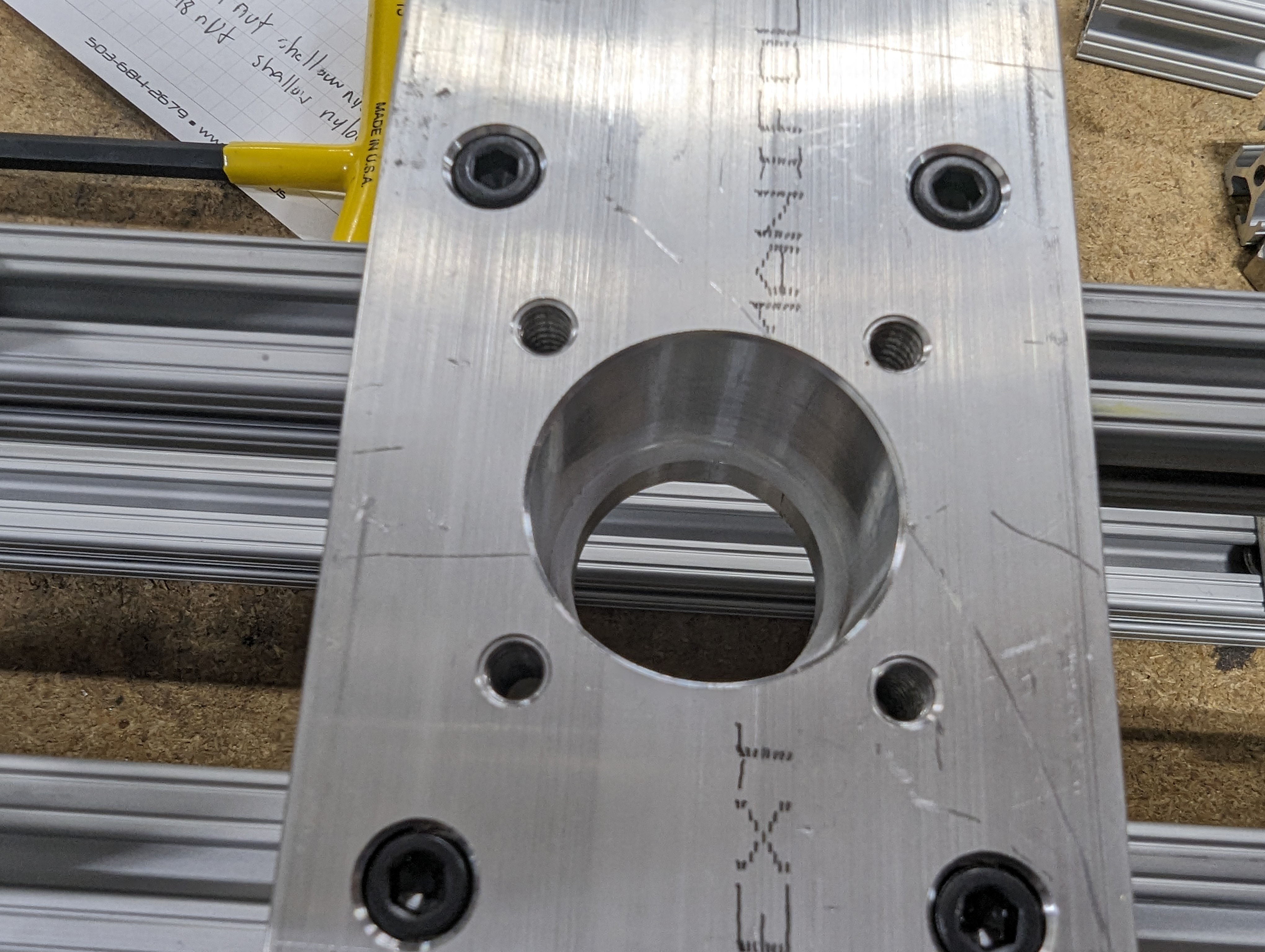
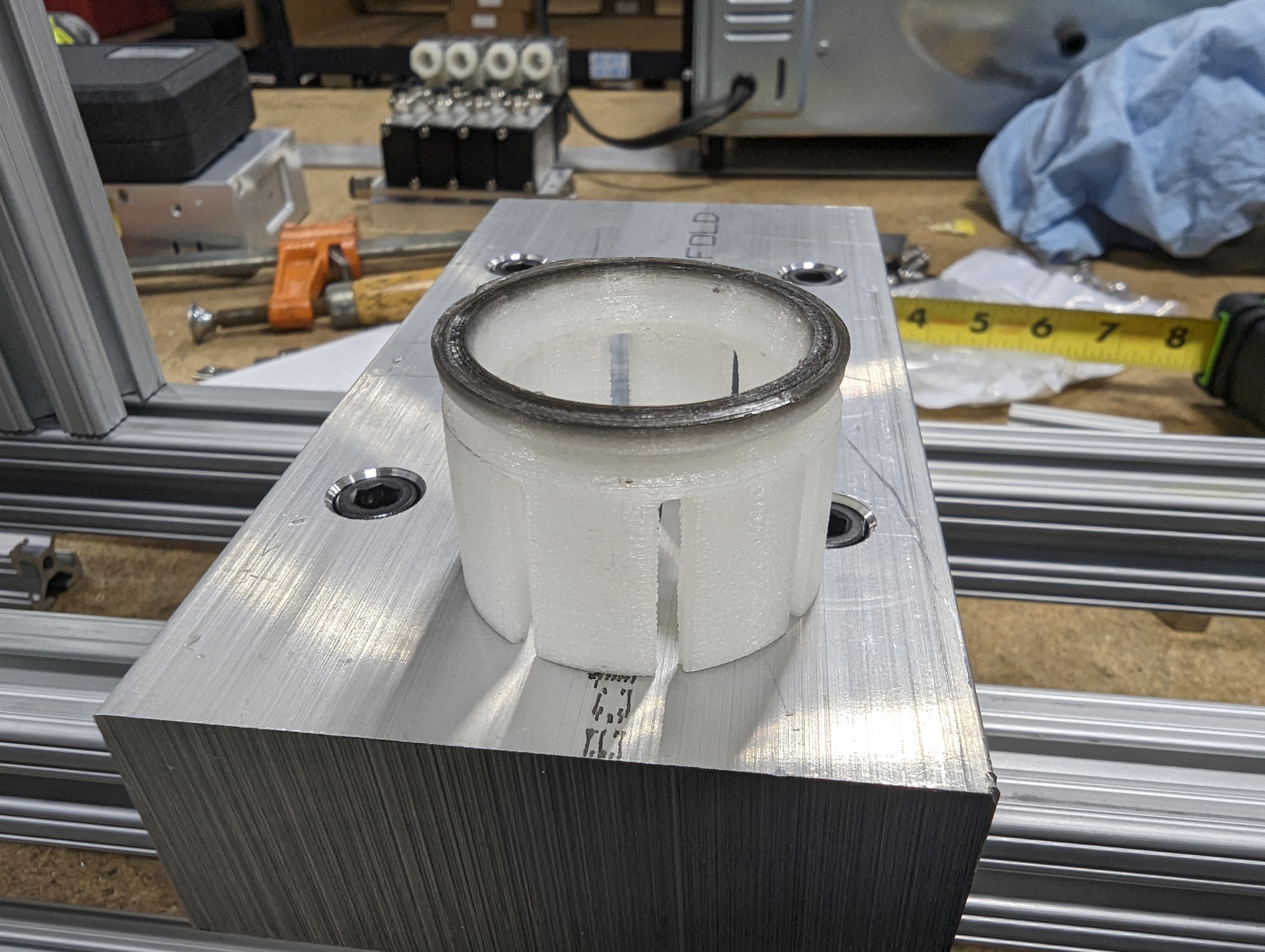
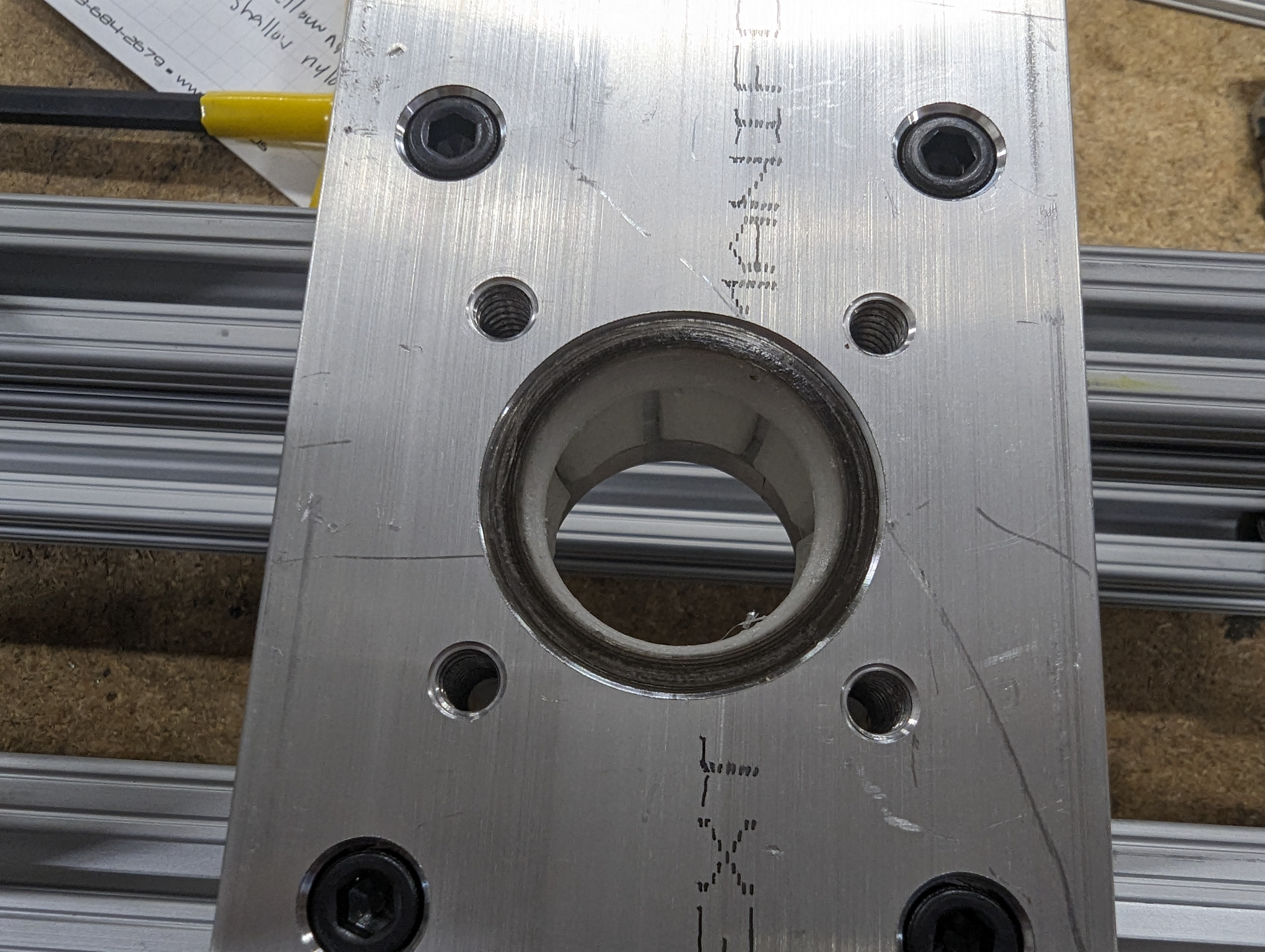
We actually make performance retaining clips for other vehicles, so Jacob had already modeled up the factory GR86 retaining clip, and we 3d printed it with nylon filament.
We didn’t end up using these straps to retain the clip.
Next up for machining was the plate that the air cylinder would mount to. We happened to already have this air cylinder from our box folder project, and it turned out to be the perfect size to allow us to really put some pressure on the shifter if we wanted. The trick was that these are designed to have a much thinner mounting plate than what we have, so we had to create a pocket on the back side to give clearance for the cylinder and hose fittings and also allow enough engagement on the main nut.
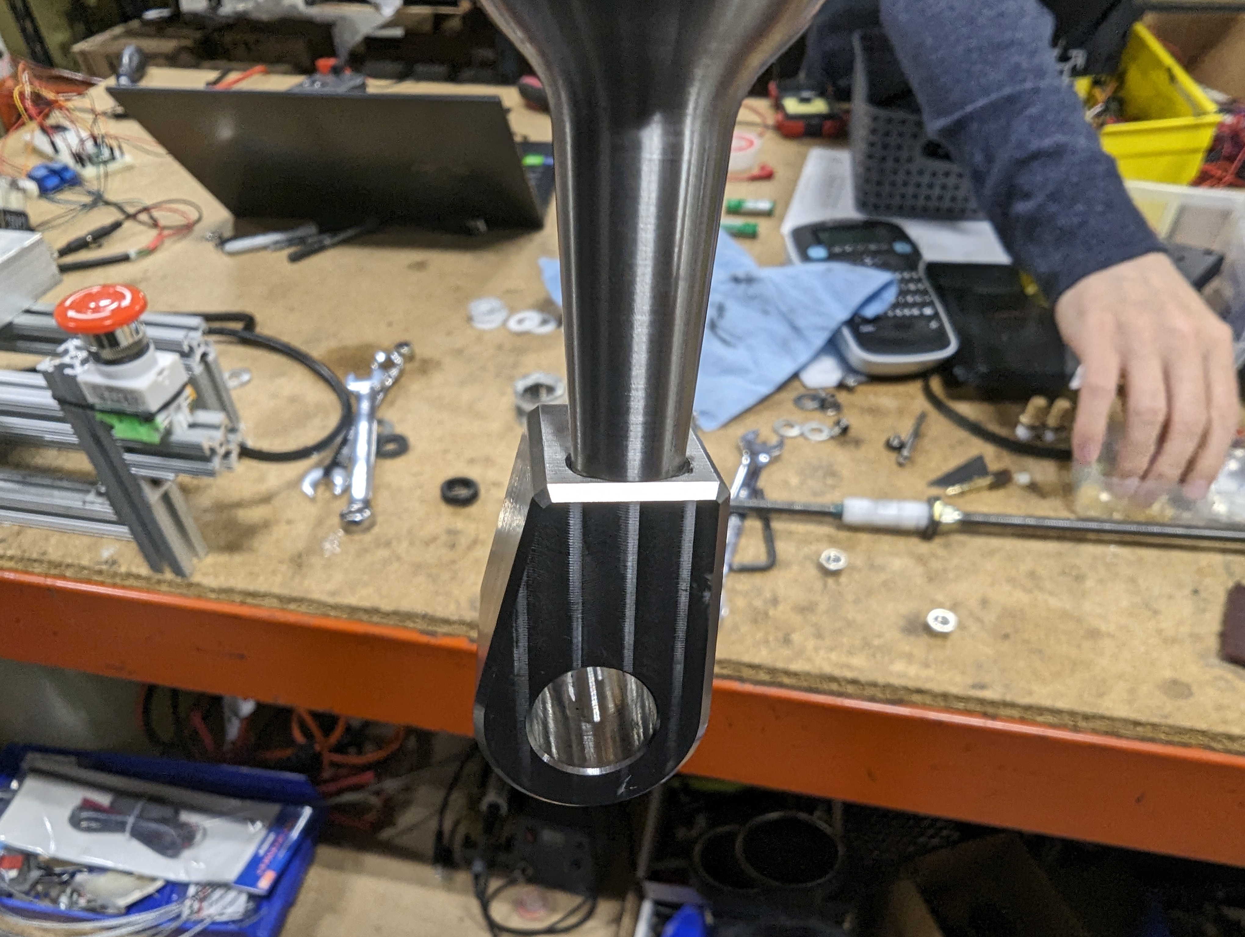
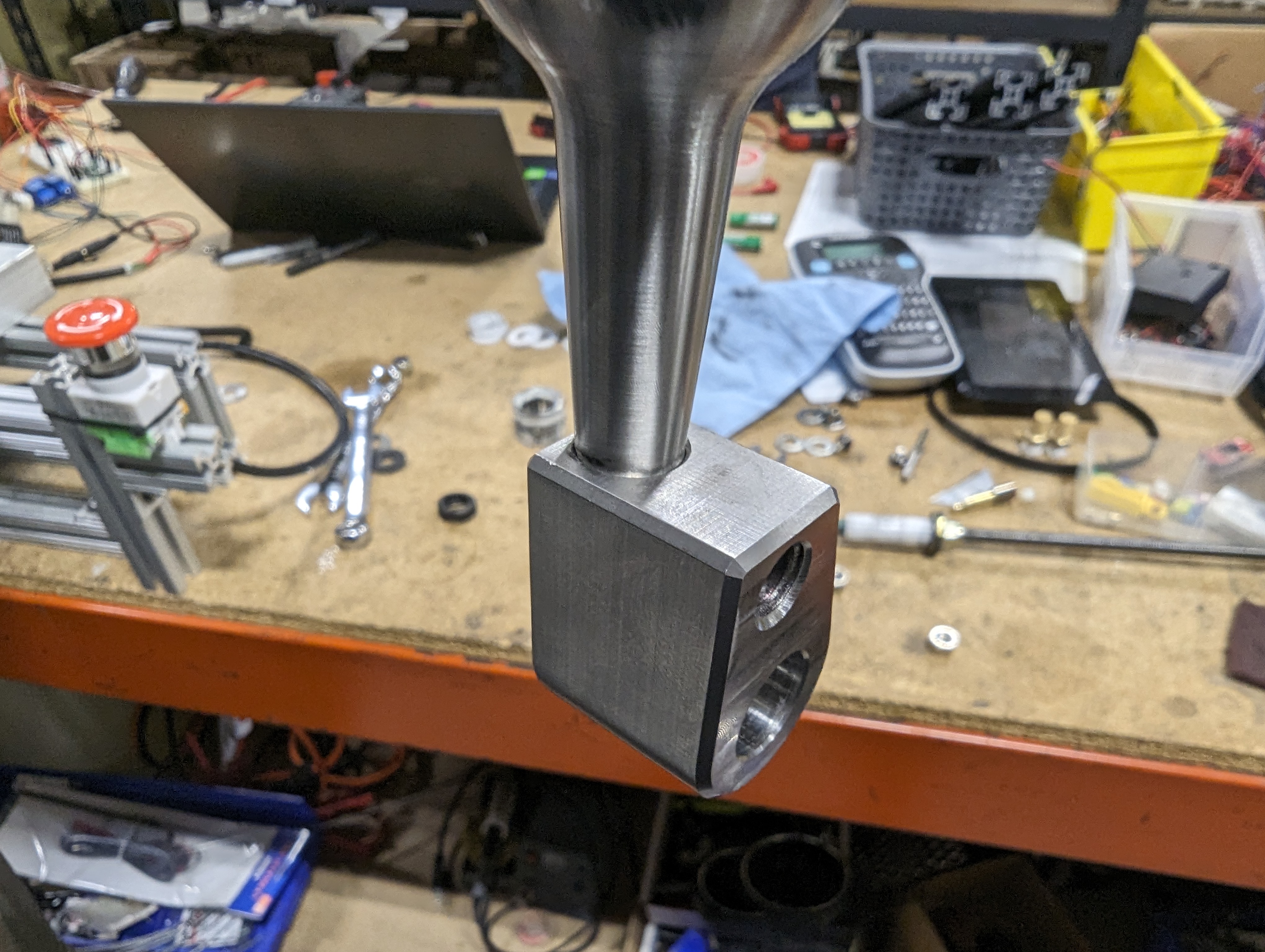
At this point the machine was already pretty sturdy and it was really starting to come together. While Jacob was machining the plates, I whipped up an end for the linkage that would allow us to attach the all-thread to the shifter. This was just a piece of box tube that I drilled a hole through and cut one side off of. I made a bushing out of the white acetal material that fit the end of our shifter, then ran a bolt through the linkage end and the bushing.

Eventually we would end up using some plastic washers to take up the space between the linkage end and the bottom of the shifter.
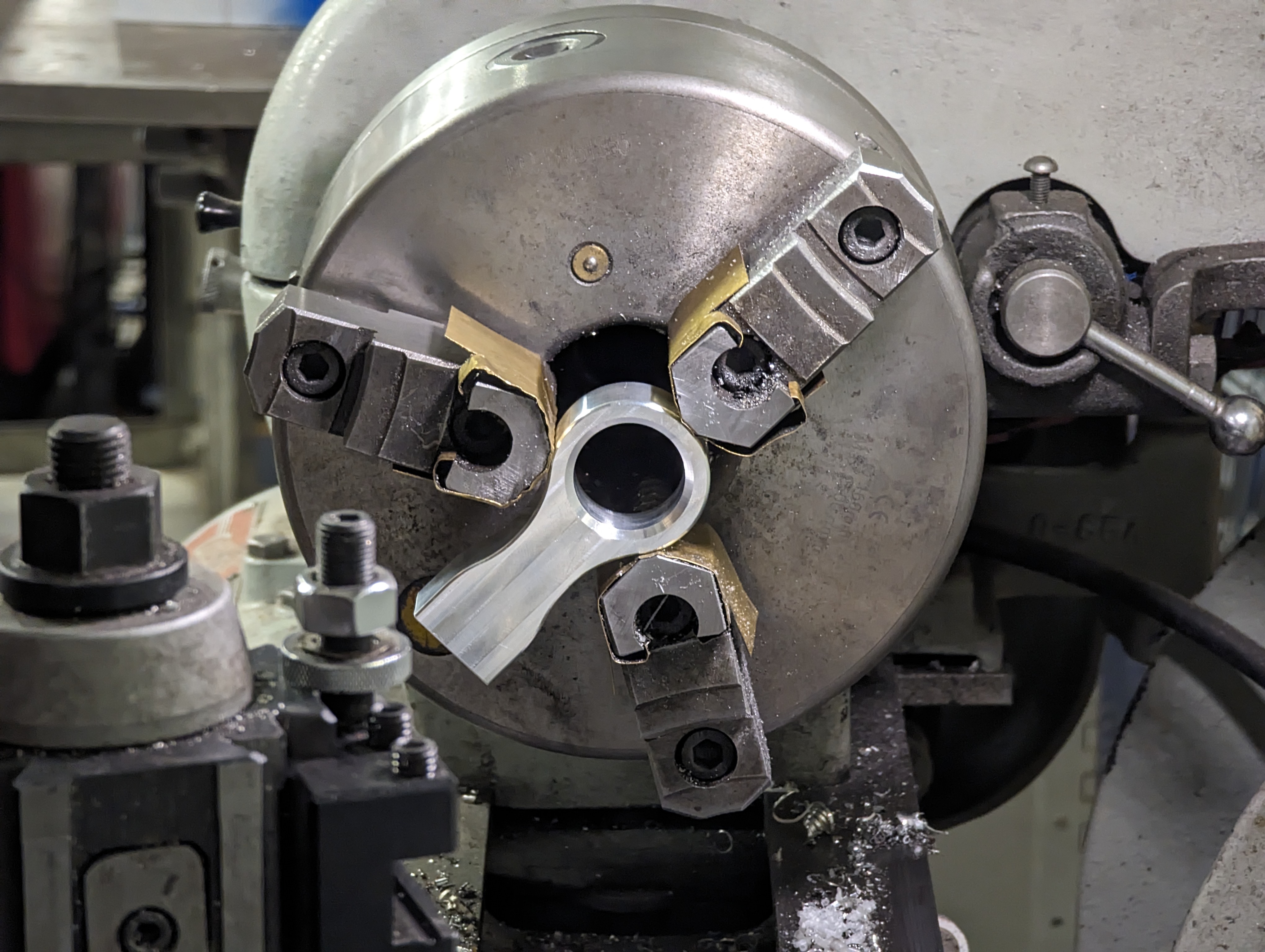
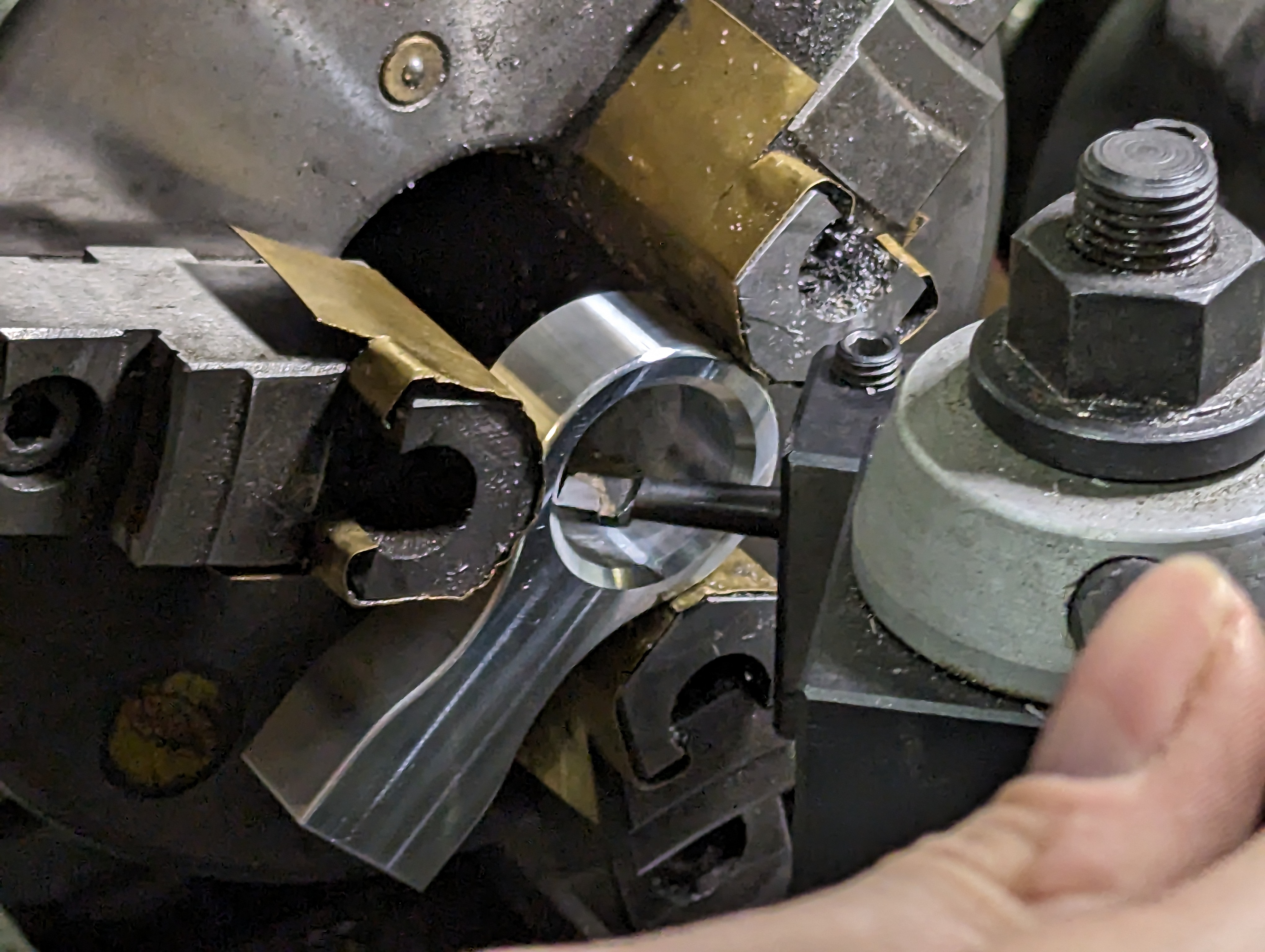
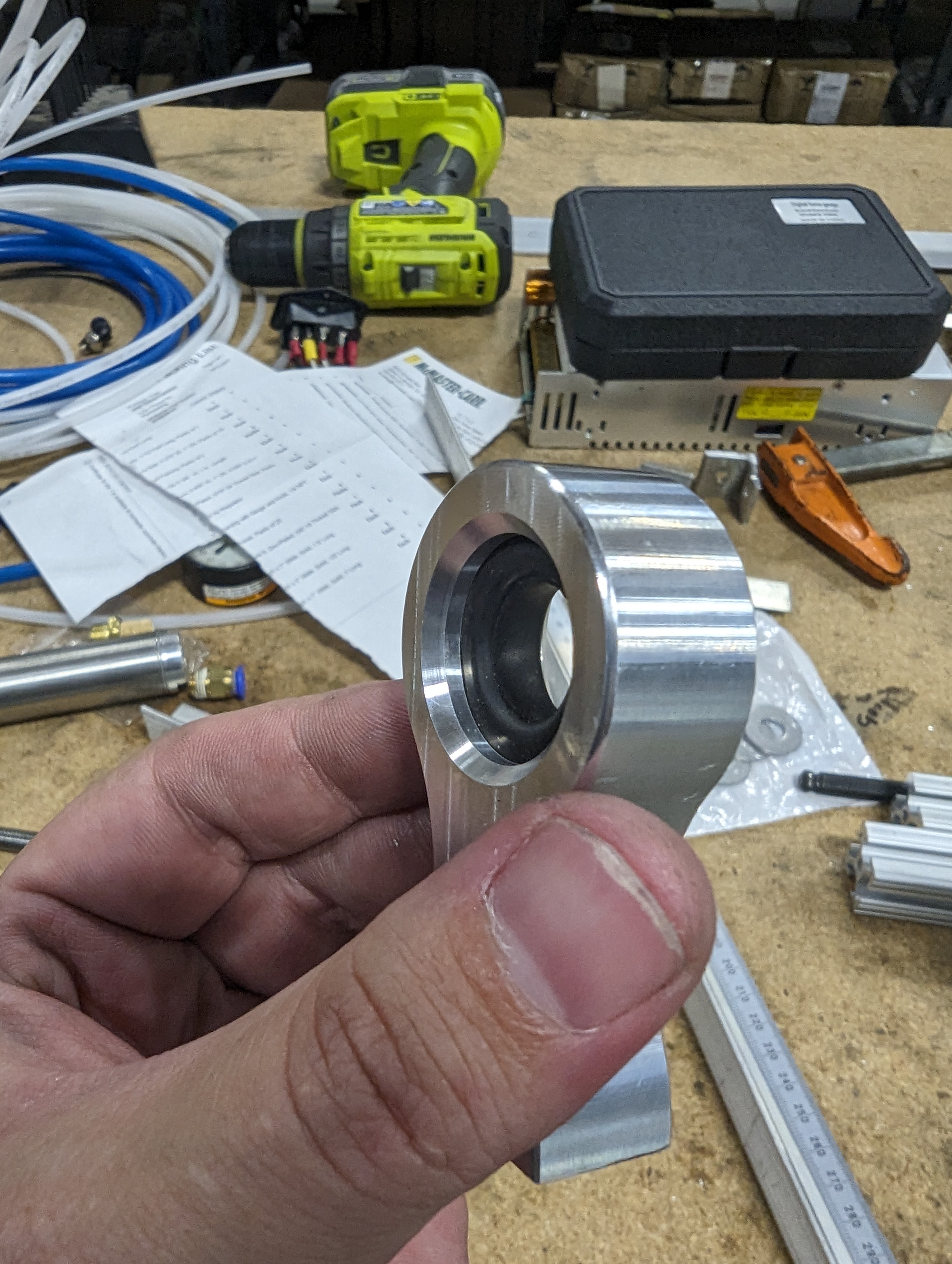
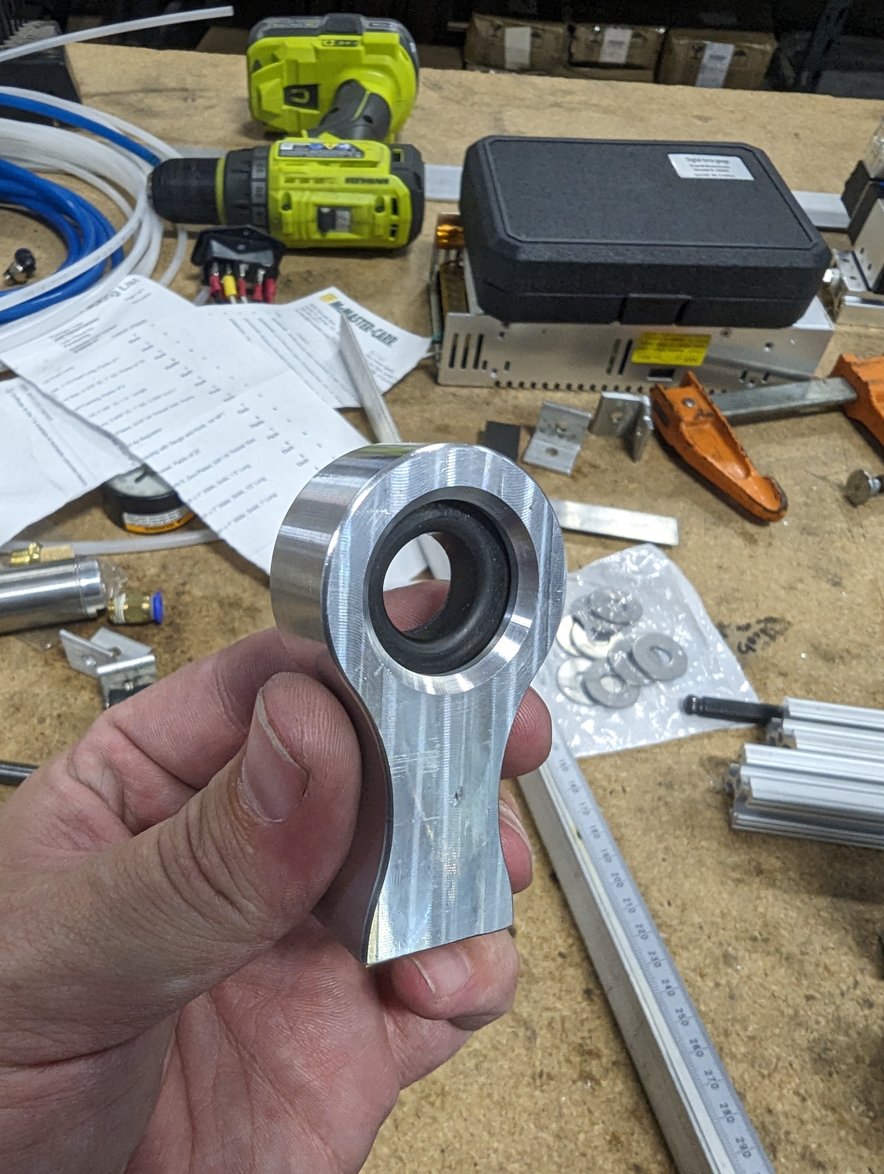
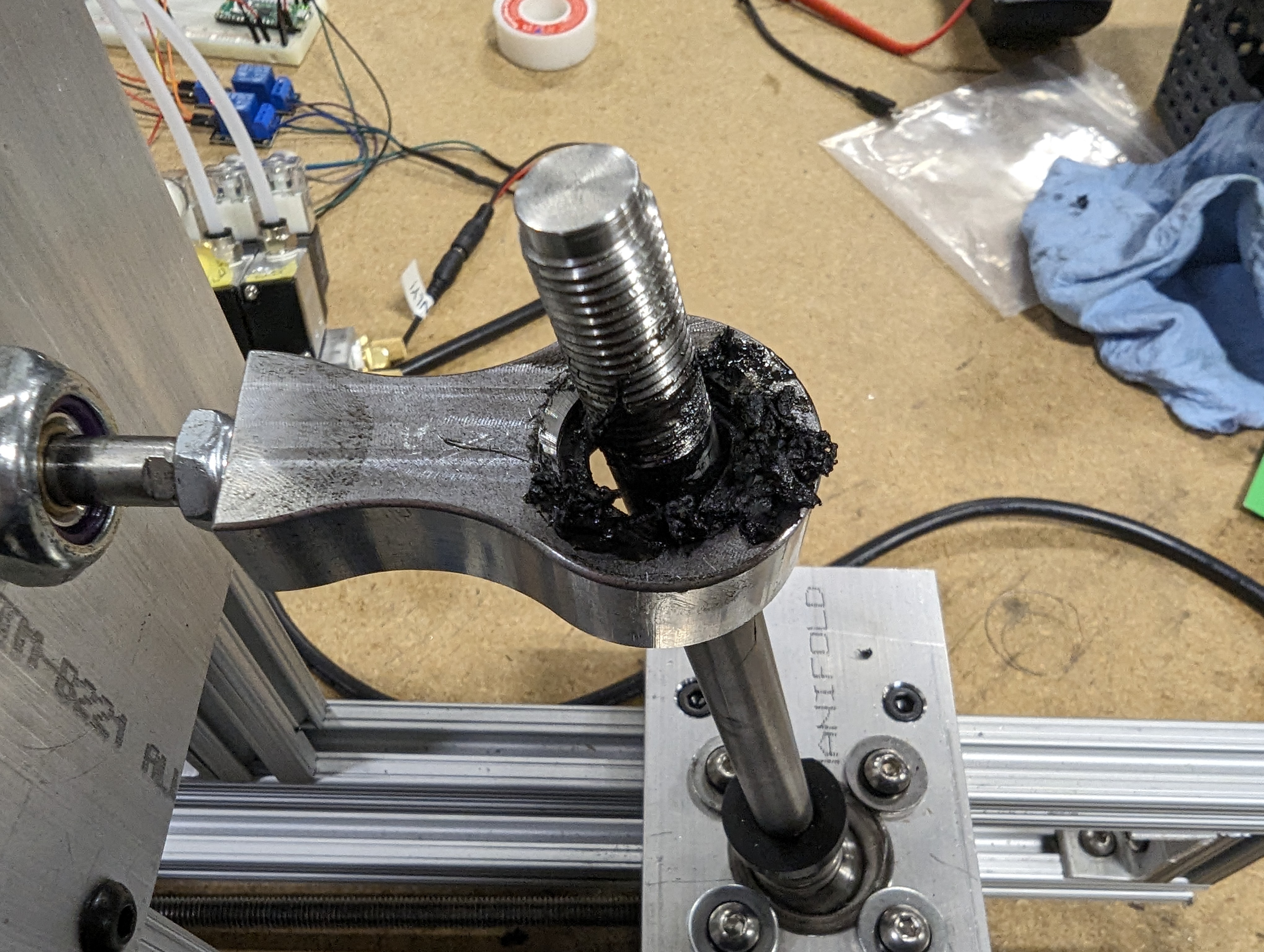
With one end of the shifter attached, we needed to figure out how we were going to interface between the air cylinder and the shifter itself. We were focused on keeping all of the forces in line with the air cylinder. We figured any deflection of the piston would limit the life of the cylinder. The problem is the shift knob travels in an arc, so whatever we came up with had to allow the shifter some freedom to move in the vertical axis. We thought about printing a “hand” that would clamp onto the shift knob, but we decided to scrounge around the shop and see if we could come up with something simpler. While digging, we came across a batch of old swaybar endlinks that were machined incorrectly. Right away we thought one of these cut in half could be perfect. If we could line the hole with something soft, we could simply run the shifter shaft through this link and the arc of the shifter movement wouldn’t be a problem.
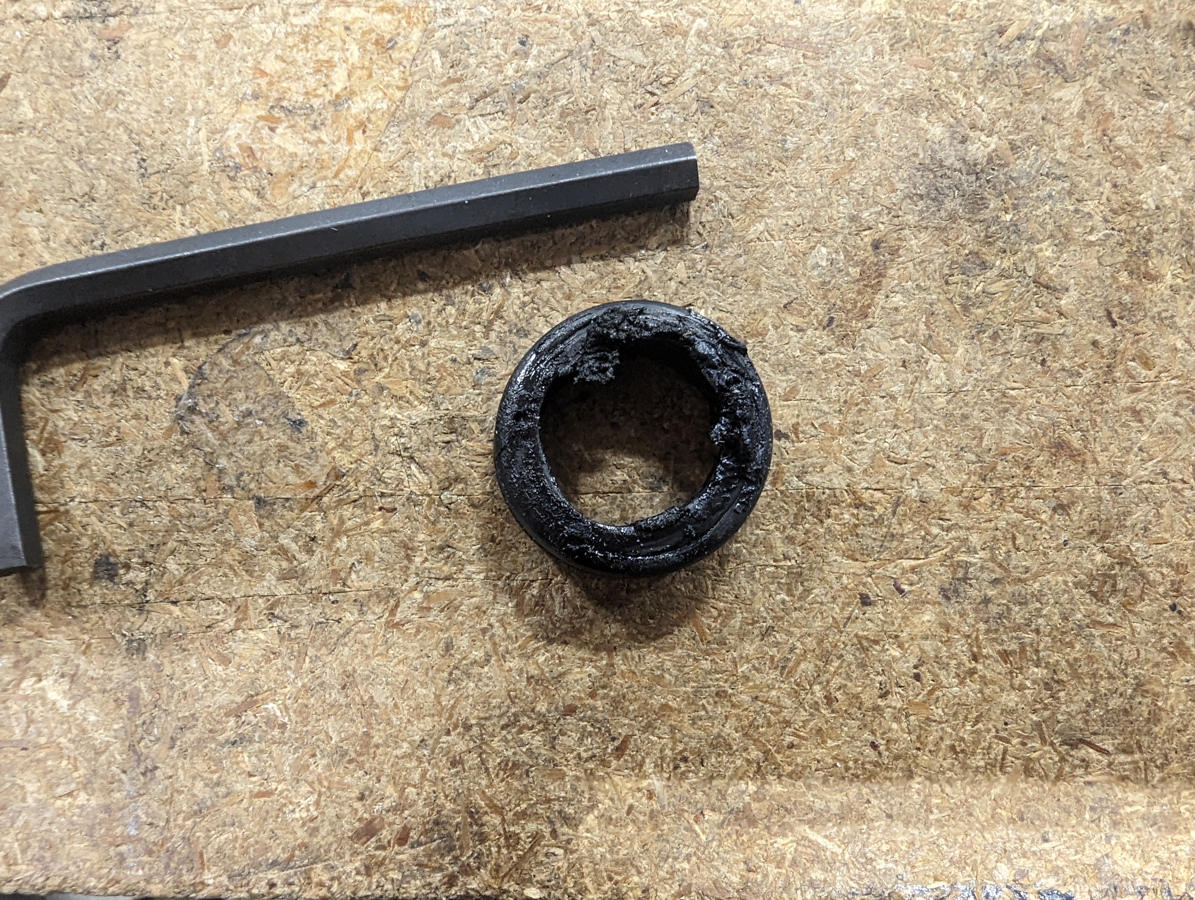
We were able to find a grommet that we use on our shift well covers that just so happened to fit into the hole in this link! It was a bit tight though, so Jacob had to pull off some fancy tricks on the lathe to form a groove for the grommet. This would also help keep the grommet in the link.
With the groove cut the grommet fit in perfectly. We were very happy with this solution when we figured it out. Little did we know this grommet would end up causing us a bunch of trouble!
For now, I just needed to drill and tap the end of this thing and we could attach it to the air cylinder.
A little dab of grease would make this mechanism work exactly how we wanted it to. (Or so we thought!) In the next photo you can also see how we ended up just using some washers to retain the retaining clip.
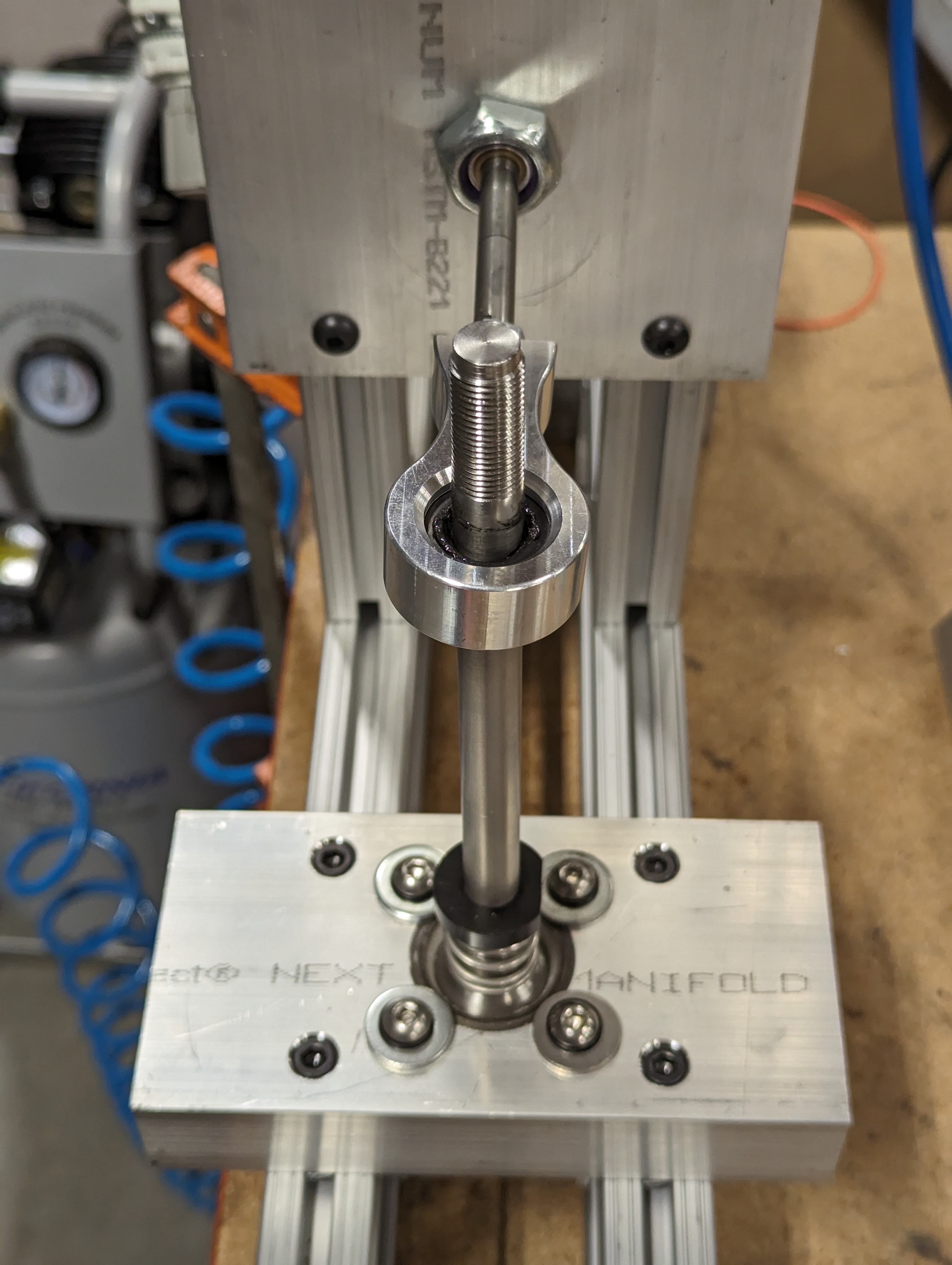
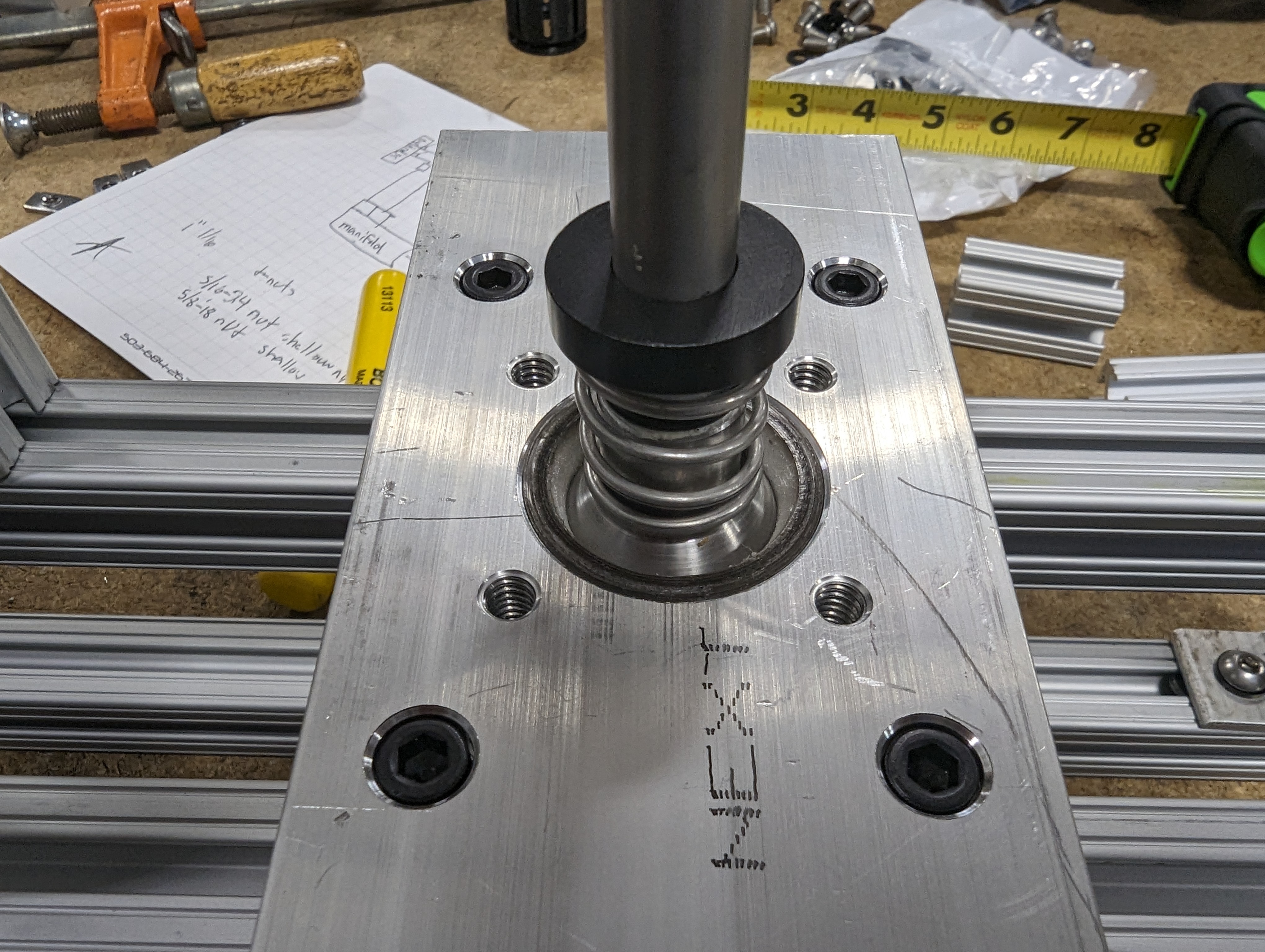
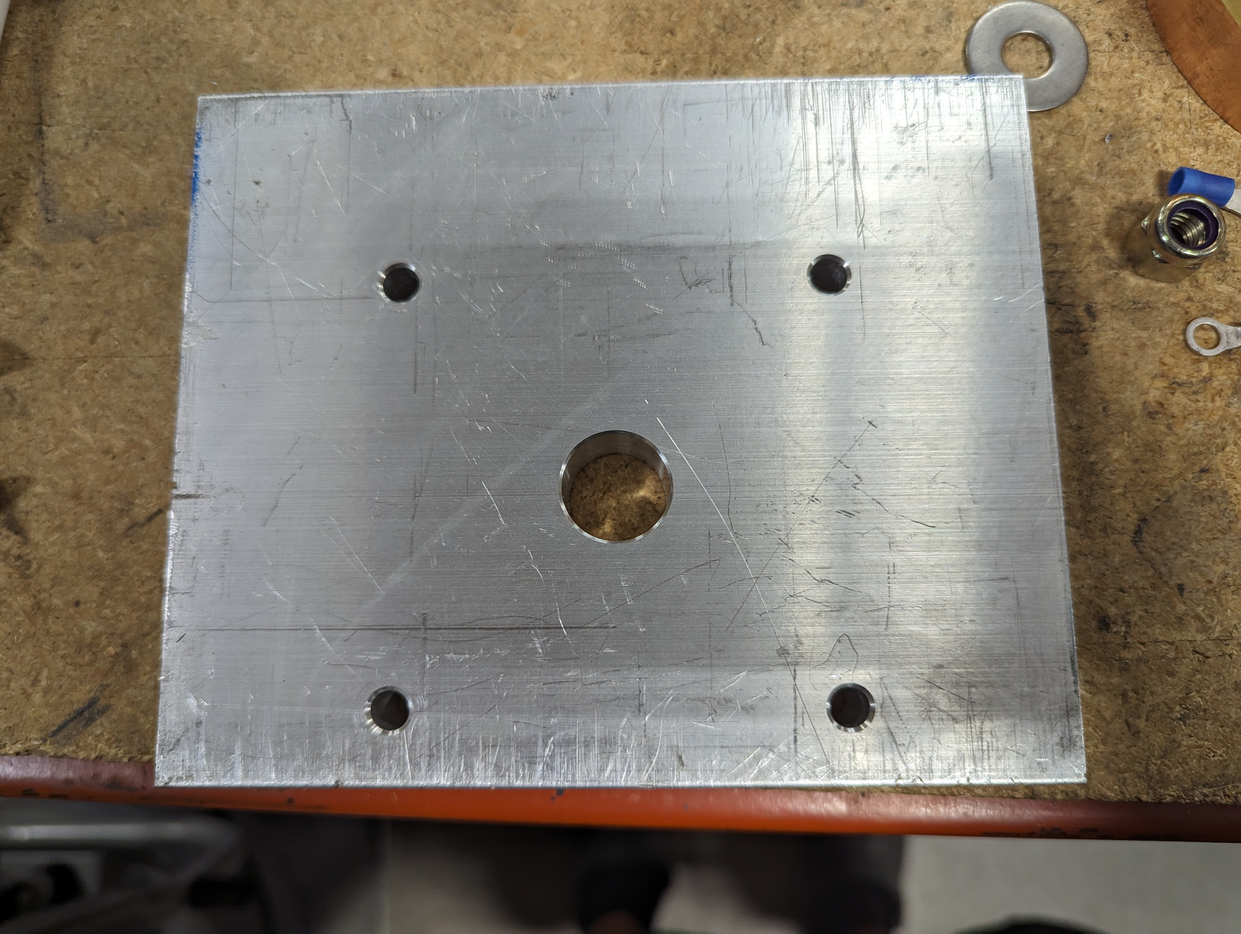
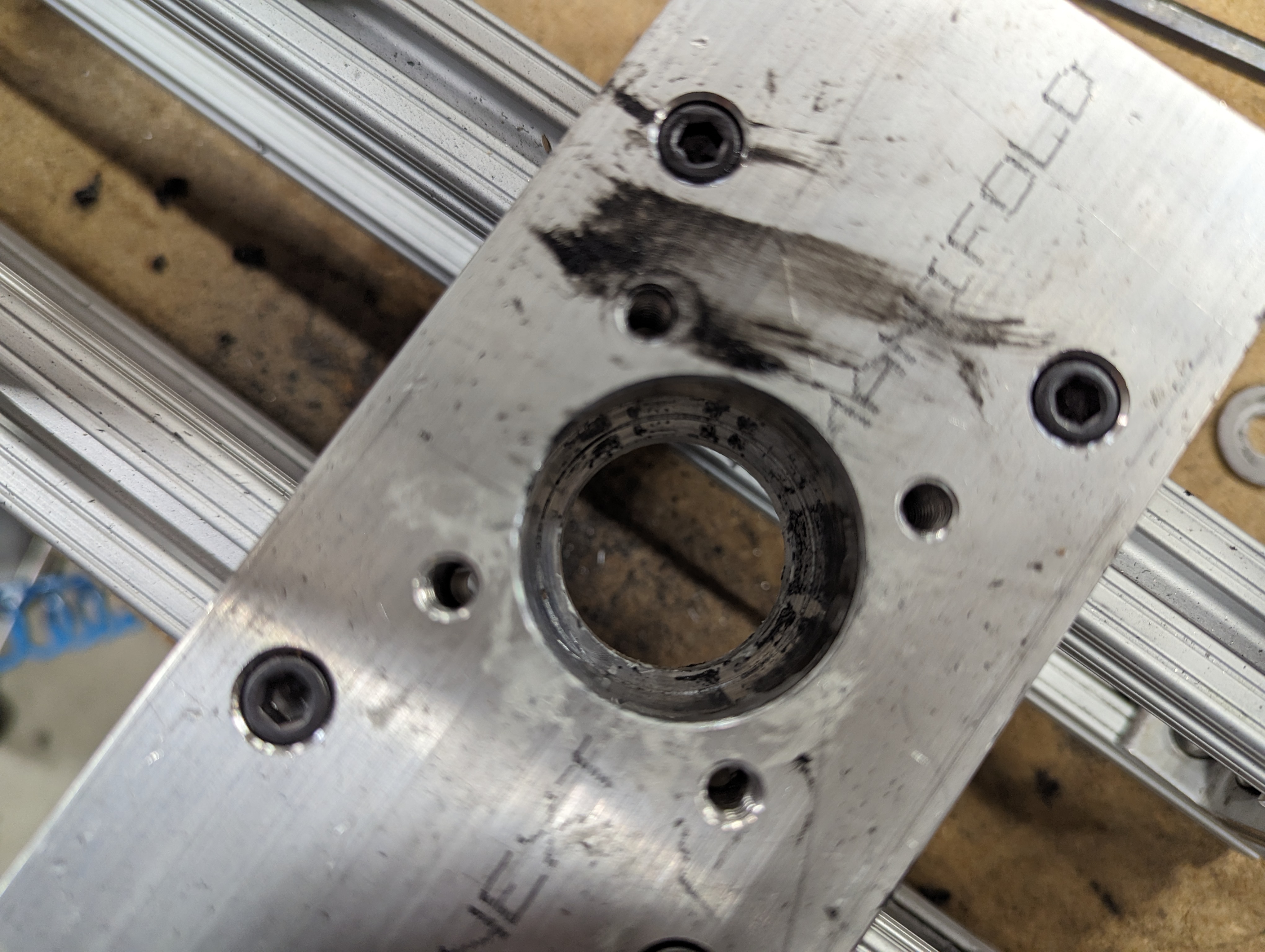
The final part of the mechanical assembly was the other end of the linkage which would pass through an aluminum plate at the end of the frame. I made another acetal bushing that matched the length we needed to simulate a full throw in the GR86. On either end of the bushing would be a rubber washer sandwiched between two steel washers. Those with a clever eye might start to figure out how we would detect which end of the shift we were at. The end plate just had a big hole in the middle with four bolt holes to attach it to the frame.
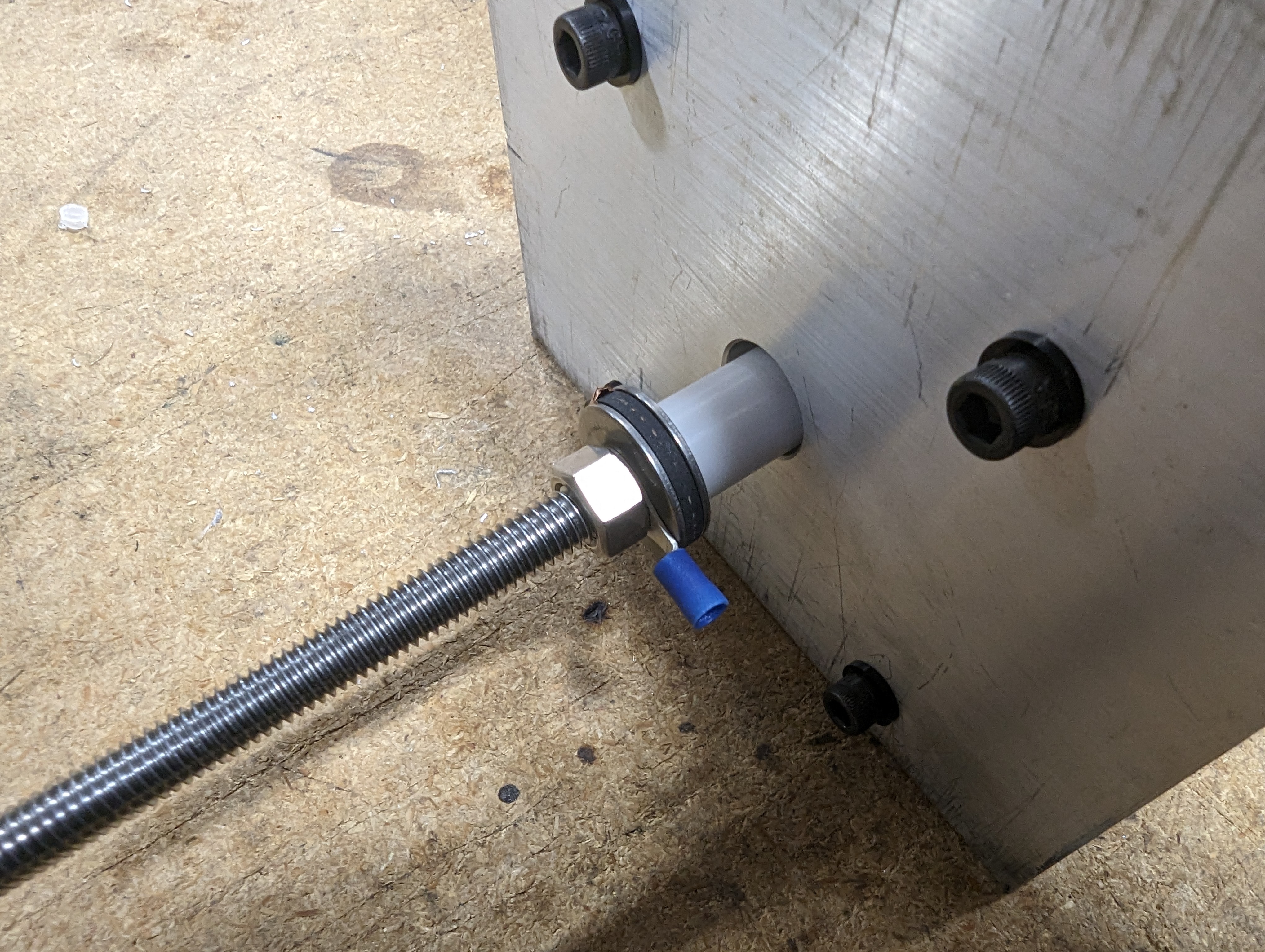
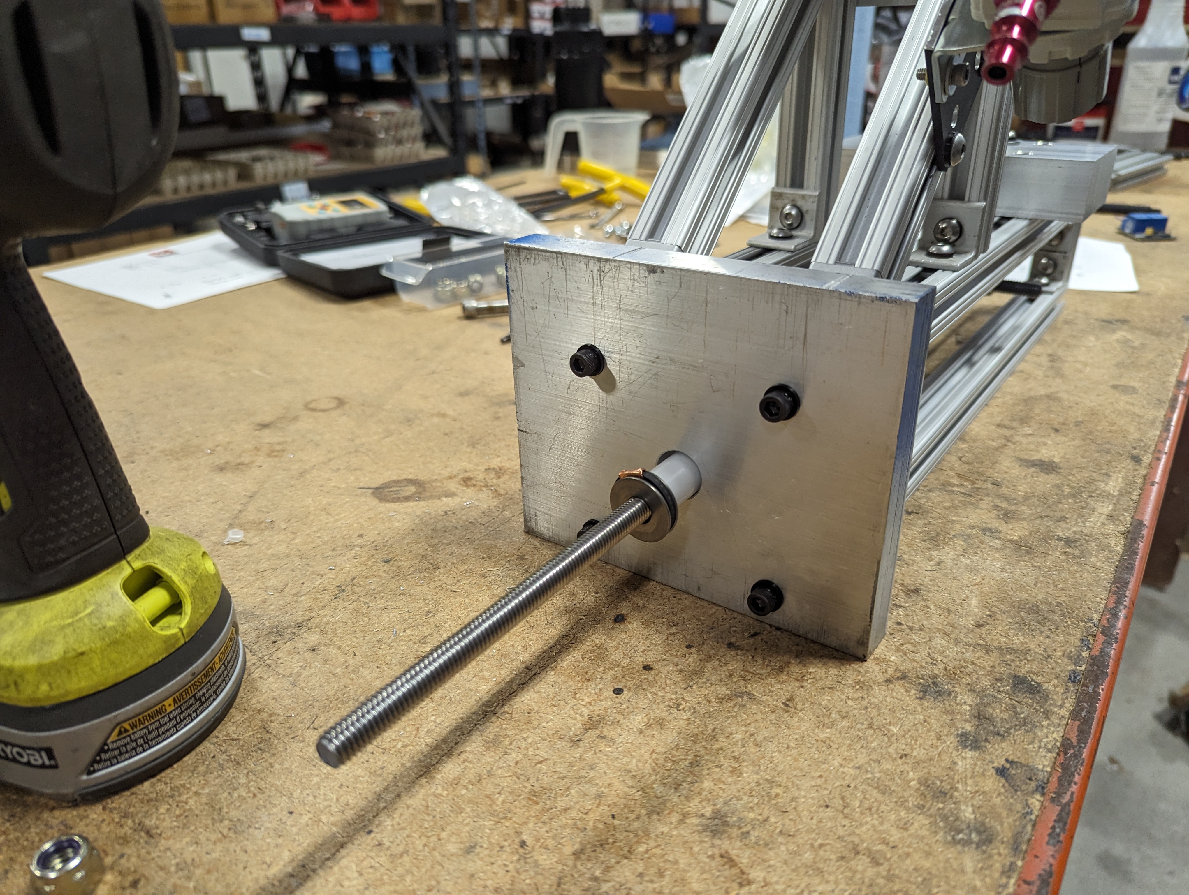
With another nut on the end of the rod, the mechanical assembly was complete! Since the all-thread is electrically isolated from the frame by the acetal bushings on either end, we could easily detect if either stop was in contact with the frame. But before we got to electronics, we wanted to get this thing all plumbed up and ready for some calibration testing!
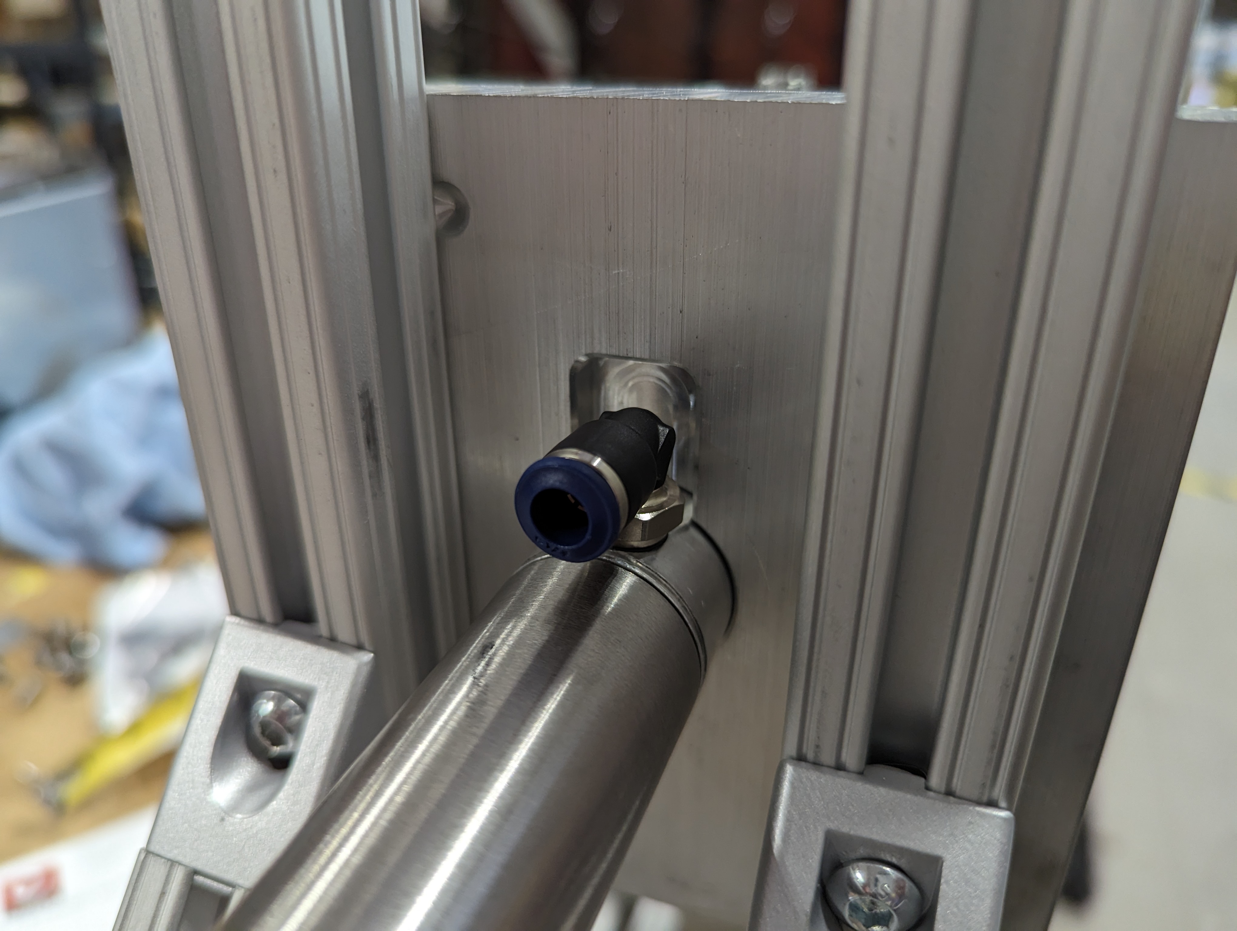
First I needed to install an air pressure regulator. The included bracket wasn’t going to work with the frame hardware, so I made a quick little adapter plate out of some scrap aluminum. It aint pretty, but this aint a beauty contest.
Then we got all of the air plumbing installed.
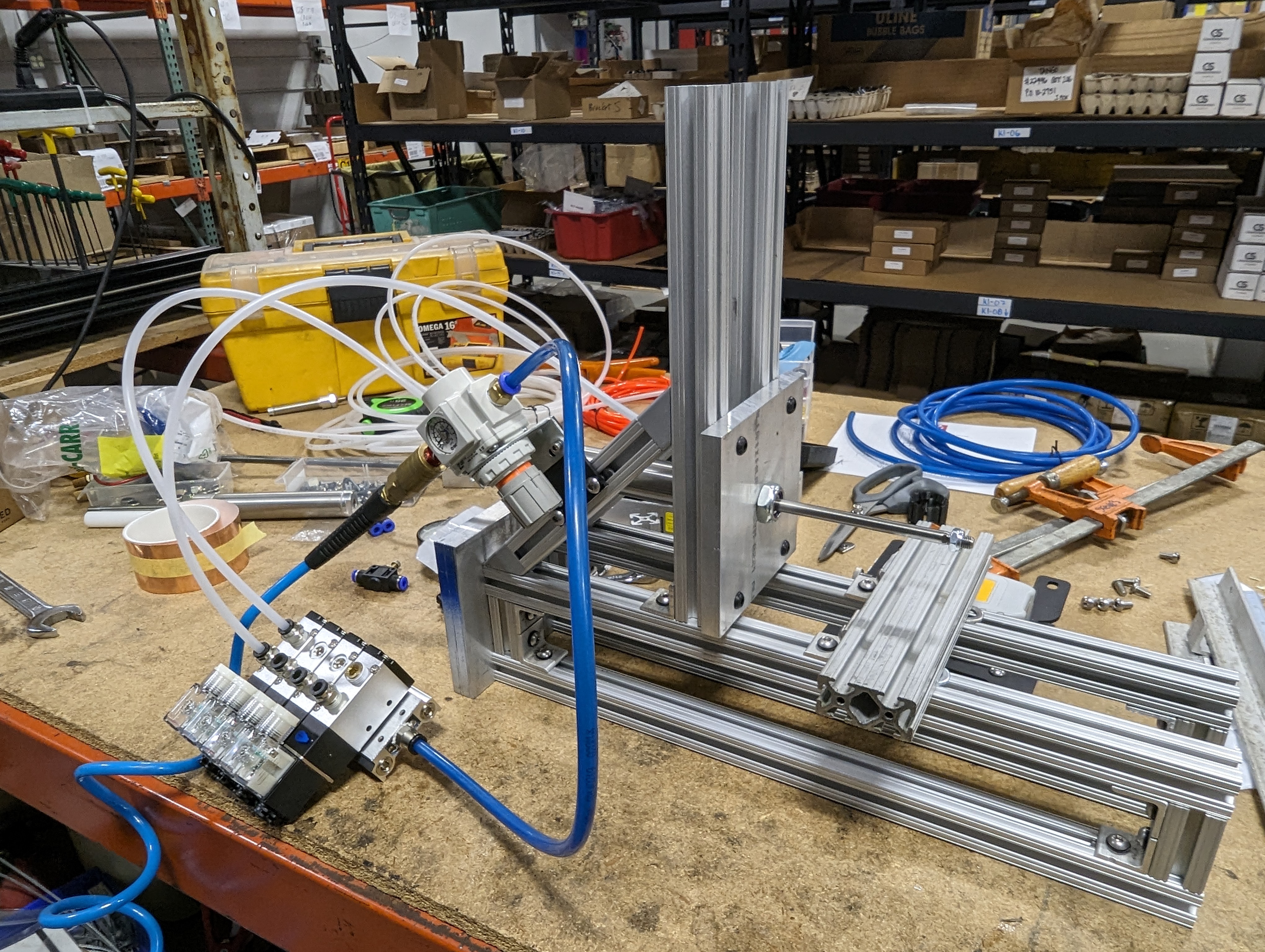
And now it was time to test the cylinder.
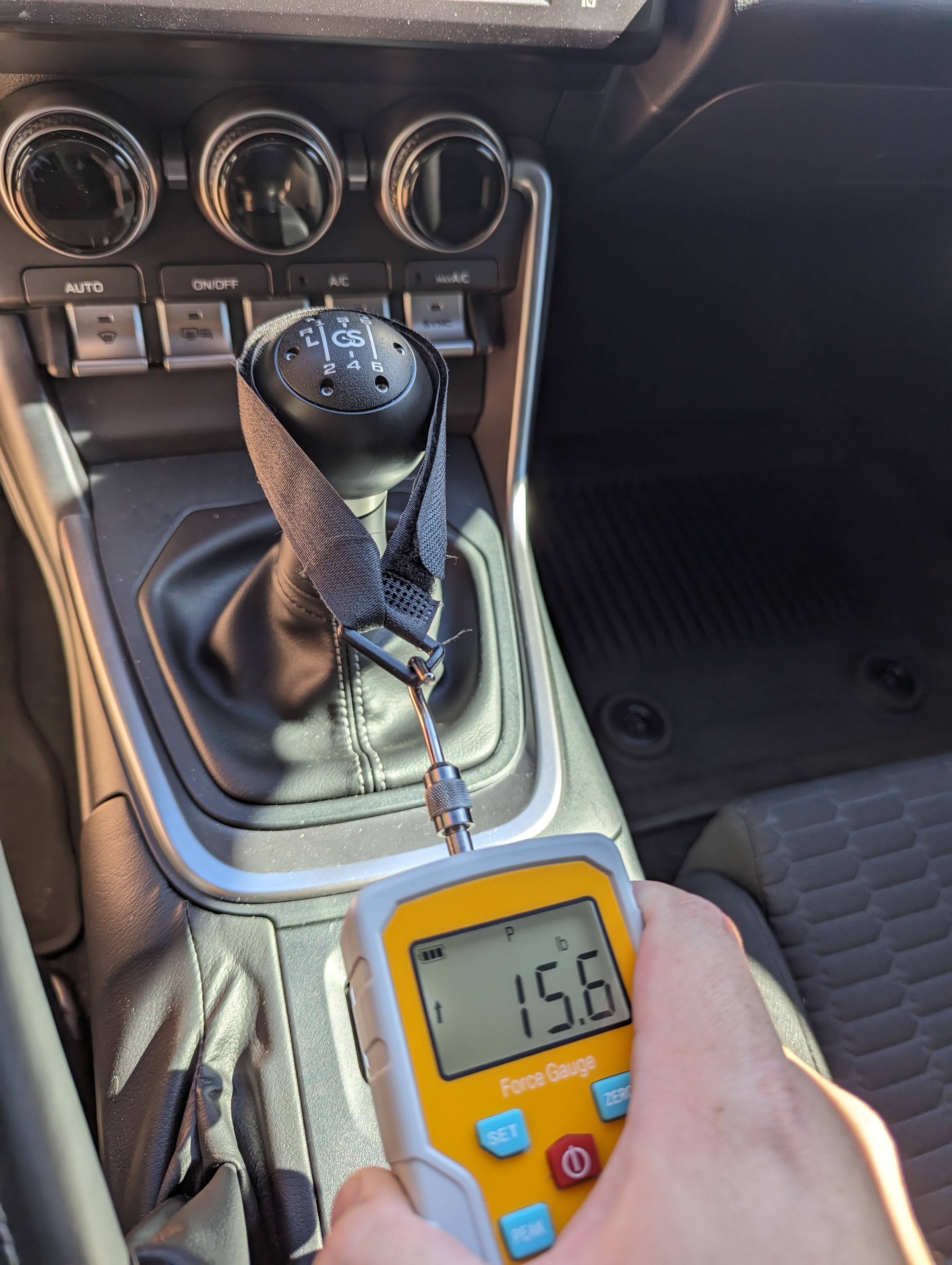
With verification that we could actuate the cylinder, it was time to figure out how much pressure we wanted to put on the shifter. For this we would need a simple force gauge which we had found online. I went out to the car and did some test shifting. I found that the minimal force required to shift the shifter was about 5 lbs, a hearty shift took about 8.5 lbs, a heavy shift took around 15 lbs, and the most force I felt comfortable applying was about 50 lbs.
With that knowledge, we decided to run our 1 million cycles at about 25 lbs, which should be well over the force that would typically be used to shift. Now that we knew what force we wanted out of the cylinder, we had to do some calibration. I quickly rigged up a plate that would allow us to mount the force gauge to the machine. The nature of t-slot framing being highly adjustable made this a very easy task.
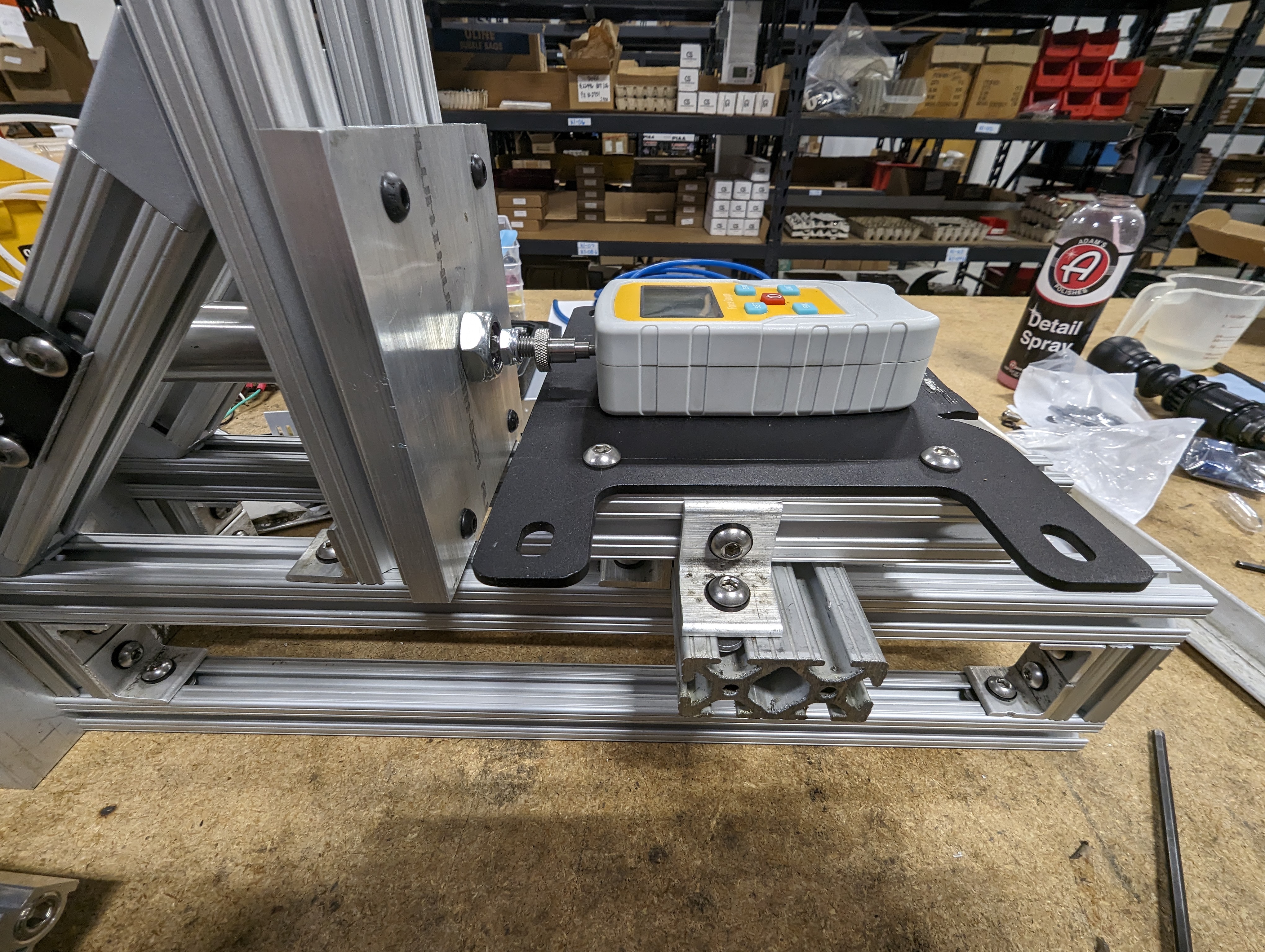
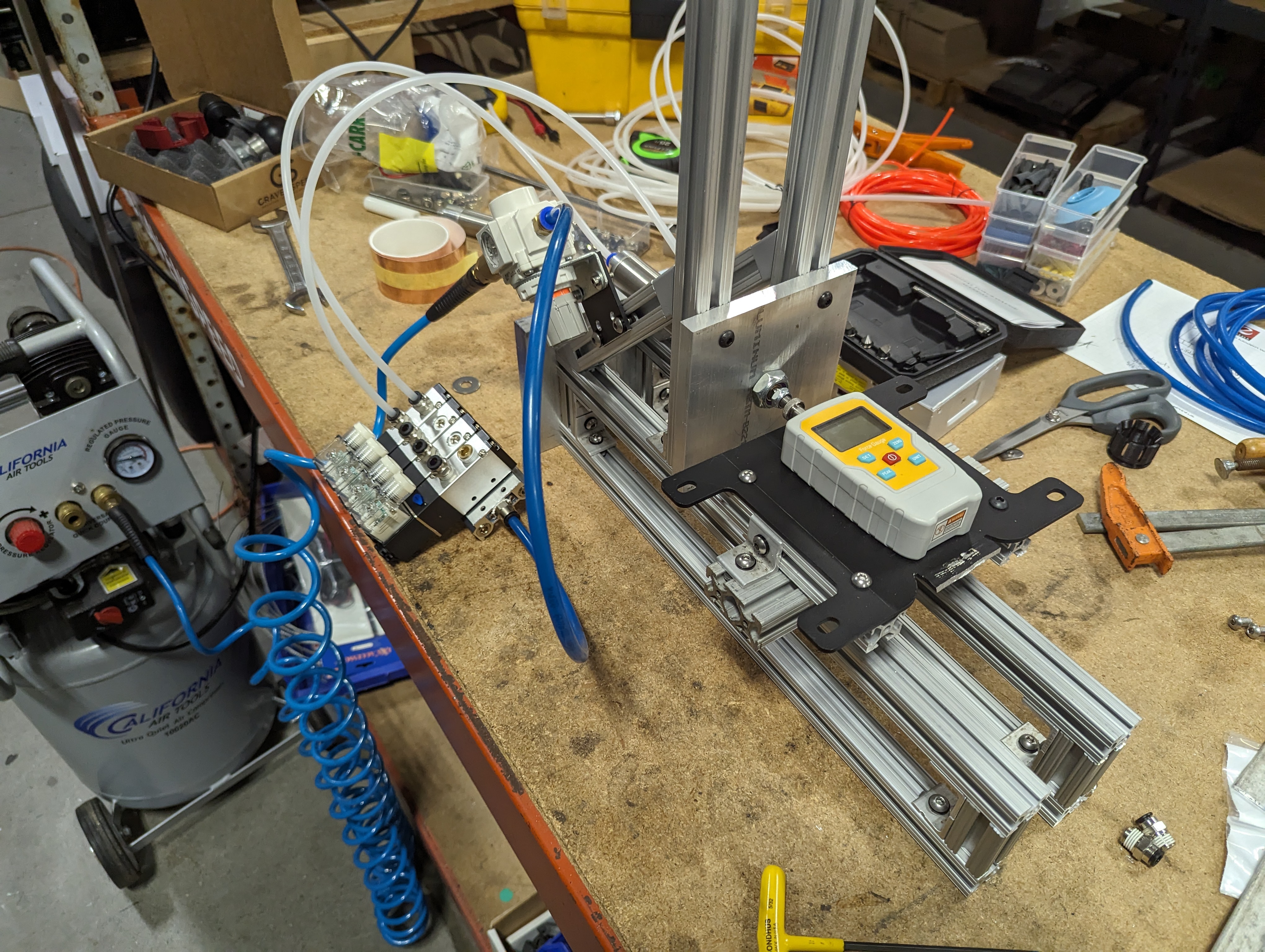
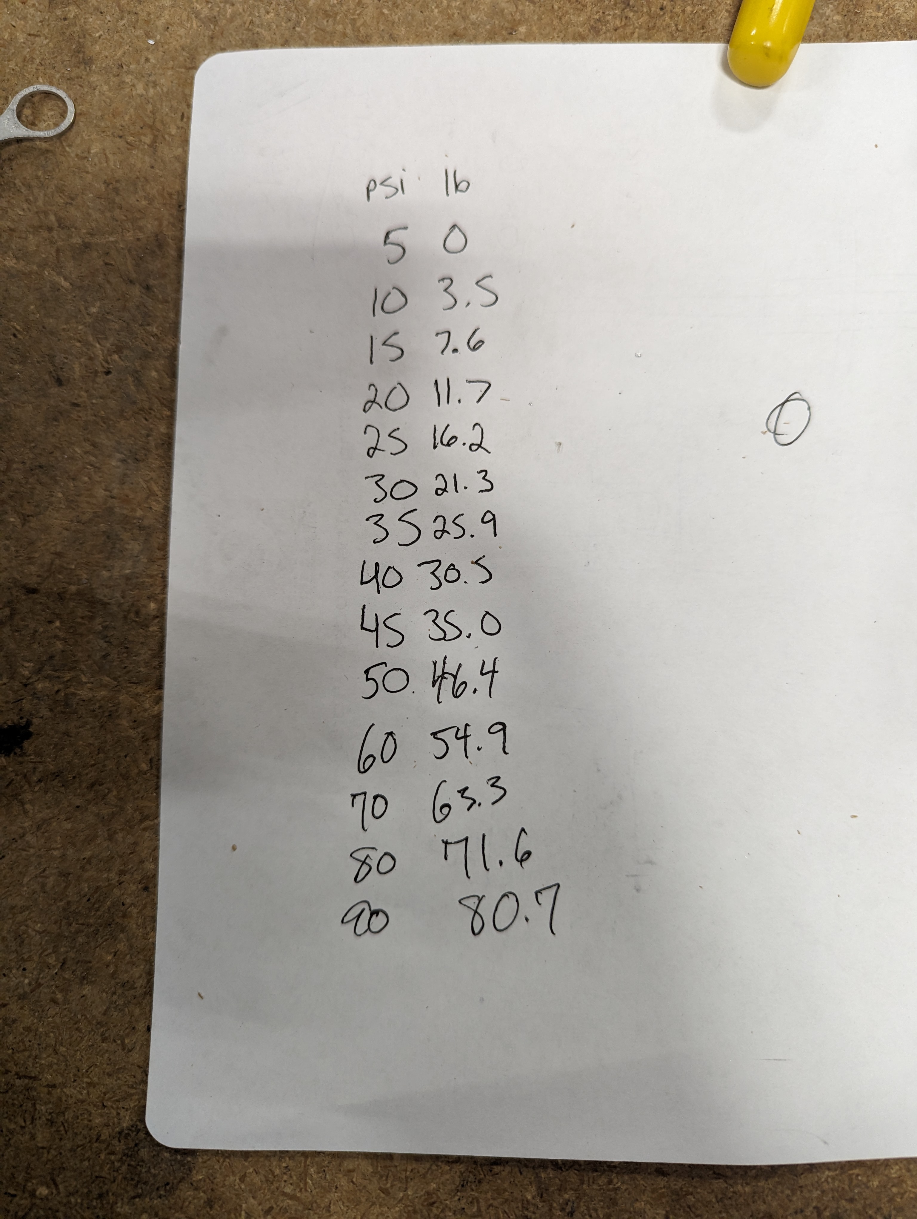
We started with the regulator set to 5psi, and recorded the force in increments all the way up to 90 psi, where we started feel that the force was well beyond what we would ever use on the machine (at least until the lifetime testing is done ?.) Once the data was recorded we used the regulator to set the psi to 25 lbs.
With this data recorded, we were getting ever so close to the end of the assembly phase. The next step was to reinstall the shifter and make sure we had each piece in the the correct location. The shifter in the 12 o'clock position should be in the middle of the cylinder stroke. We also needed to adjust the position of the stops to ensure that we would bottom out on the stops and not on the cylinder, which would be very bad for 1 million cycles!
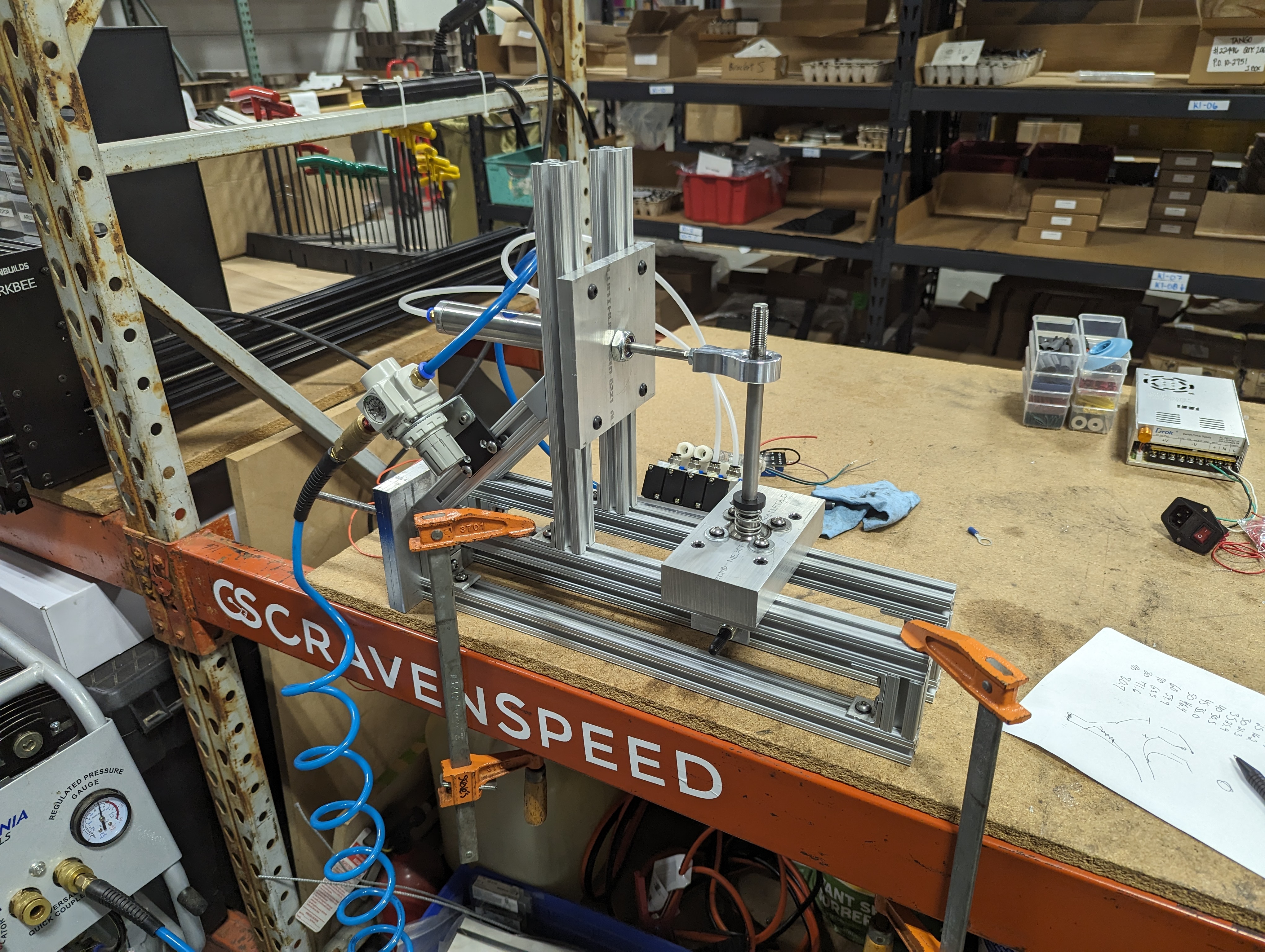
Finally we could test the functionality of the whole machine for the first time! We started at 5psi, which wasn't enough to actuate the lever fully. We slowly bumped it up till we knew the target of about 34 psi would work.
At this point we knew that the machine was at least mechanically functional! Now it was time to dive into the electronics. While some of us have minimal experience with Arduino, we knew Tristan would be able to get the software running as quickly as possible, and we knew we wanted the machine to report it’s status in our back end software, so we left this part up to him. He decided to run the machine on the Pi Pico W, since he is more familiar with Python and we needed on board wi-fi.
The hardware side was quite simple. We would use one relay to solenoid combo to pressurize the extend side of the cylinder, and then another combo to pressurize the retract side. We used a manifold that we already had from the box folder project. Then we would simply wire up the machine so that it would ground out a signal pin if either stop was in contact with the frame. This would verify for us that when the piston extended or retracted it successfully reached the end of its travel. We later realized that this configuration basically did nothing for us, but we’ll get to that!
The setup was quite simple, just a wire attached to one of the steel washers, which had some conductor connecting it to the other washer that would be in contact with the frame.
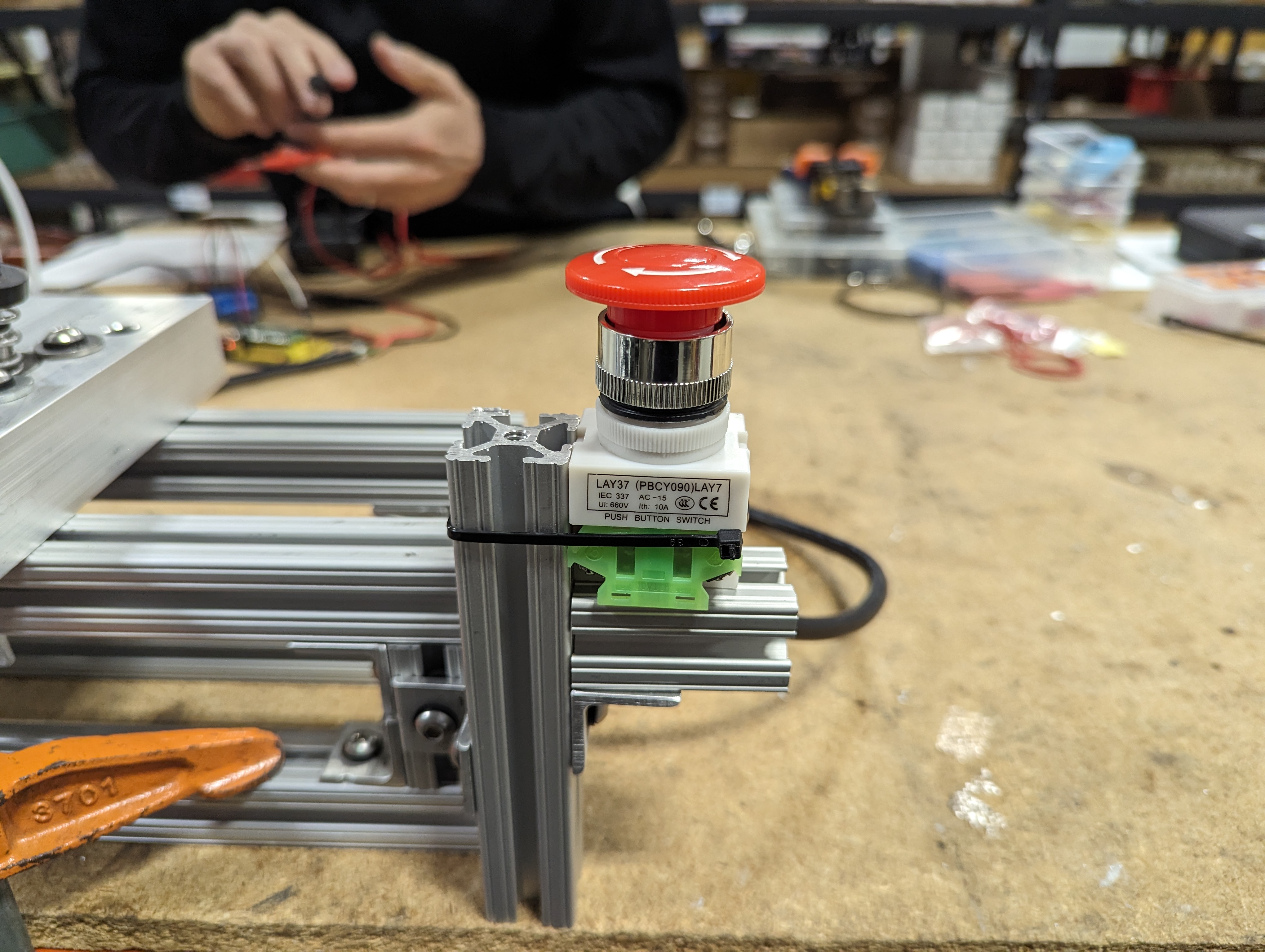
For power we just found some standard electronics power supplies we had on hand. One 5v for the Pi Pico, and one 24v to power the solenoid relays. We also wired in an emergency stop switch for the solenoids.
On the software side of things our plan was simple: Pressurize the extend side of the cylinder, wait for the signal that the stop is touching the frame, delay just a tick, then release the extend cylinder and pressurize the retract cylinder and so on until we hit 1,000,000 shifts. We would stop every so often to upload the count to send a status report to our web software. I really wanted to make sure we exceeded the typical use of the shifter, so even when the shifter hit the stop, we continue to apply force for a given time until it shifts the other way.
We finished that final assembly on Friday, and Tristan planned on writing the program over the weekend so we could start testing Monday, so that’s the full build in just 4 days! Tristan arrived on Monday with a fresh program and we plugged everything in to test running the machine off of the Pico for the first time!
Aaaaaanddd it didn’t work! Turns out our understanding of the Pi Pico wasn’t quite up to snuff just yet. I don’t remember all of the issues we ran into but I’ll list what I can. Our biggest mix-up was assuming that all of the pins on the PICO defaulted to a LOW state when in reality some are default LOW and some are default HIGH. In a more basic sense, some things were turning off when we told them to turn on and were on when we thought they would be off, but not all of the pins behave this way, so it was very confusing at first. This wound up sending us chasing all kinds of issues that we couldn’t understand. Our other major issue seemed to be related to version control between python and the libraries/other software we were using. Because of this our Pico wouldn’t connect to our wi-fi when it wasn’t plugged into a laptop and was running on the external power supply. We ended up a bit stuck and spent the next two days fixing issues only to discover another one.

But through all of this process we learned a lot and eventually we were able to get the machine running on it’s own that Wednesday!
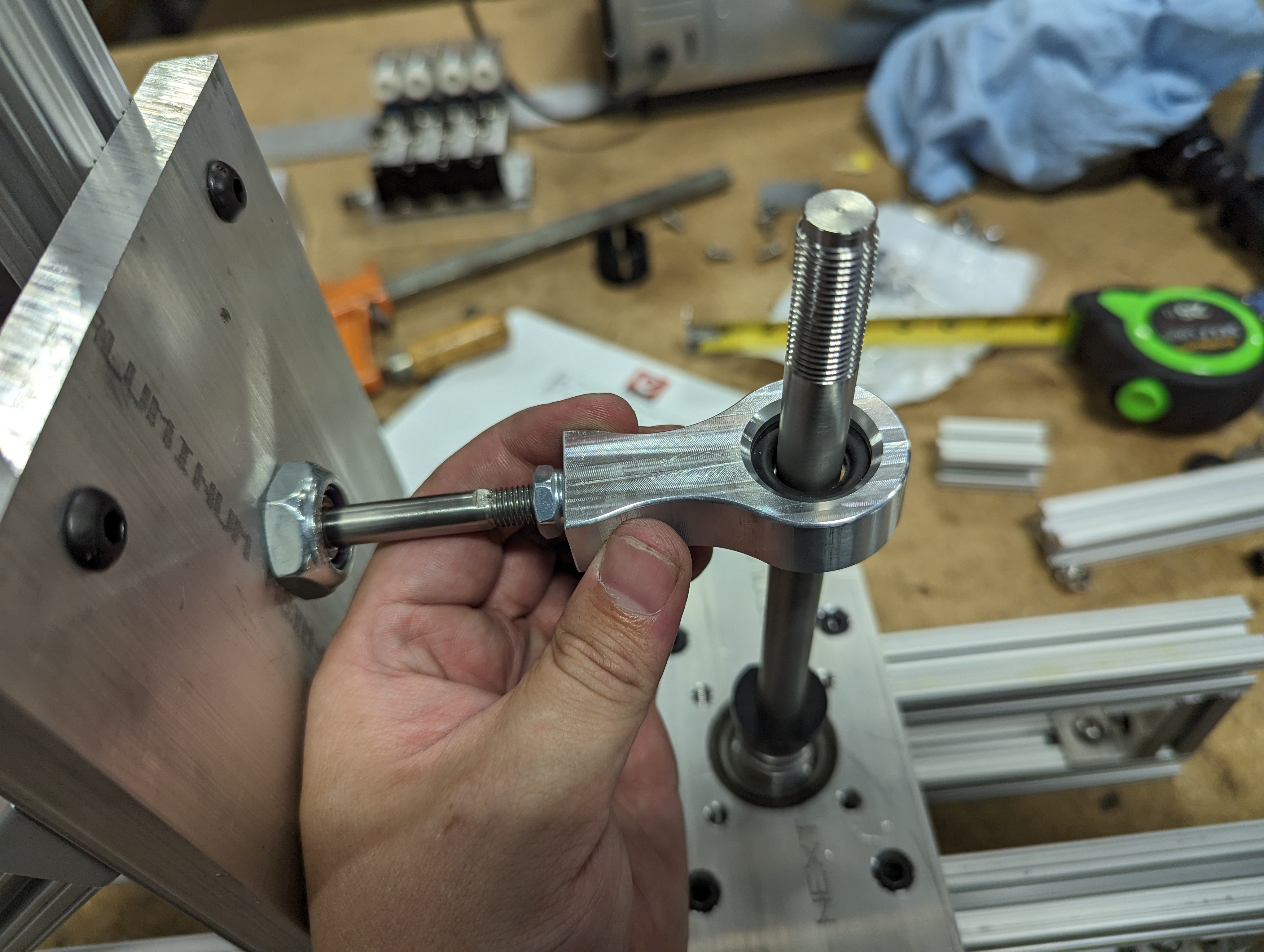
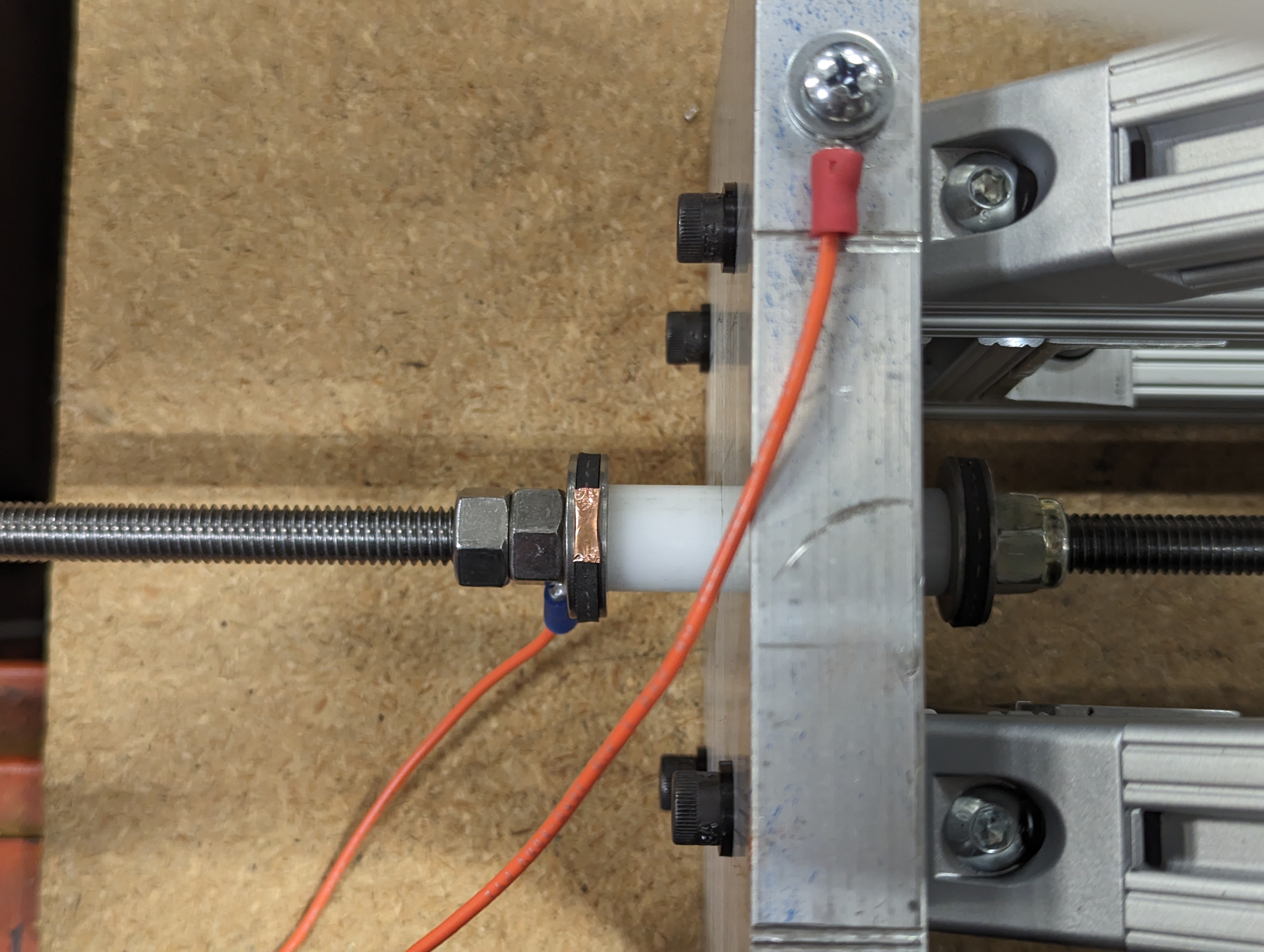
Once we had the machine running on it’s own, we realized a logical error with the way we were detecting faults. We could only detect if the linkage was against a stop, we couldn’t detect which stop was bottomed out. So theoretically, if there was an issue with the shifter that caused the linkage to become disconnected with one of the stops touching the frame, the machine would just keep on trucking since the check to keep shifting is just that one of the stops should be in contact with the frame. We thought about this for a few minutes and came up with a simple plan. With the current setup, the linkage was isolated from the shifter and frame by acetal bushings. All of the metal hardware on the all-thread would be continuous. If we simply isolated one of the stop washers from the all-thread, we could attach a wire only to that washer to detect which stop the machine is bottomed out on. To accomplish this I simply added some heat shrink tubing over the section of the all-thread where the washer would ride.
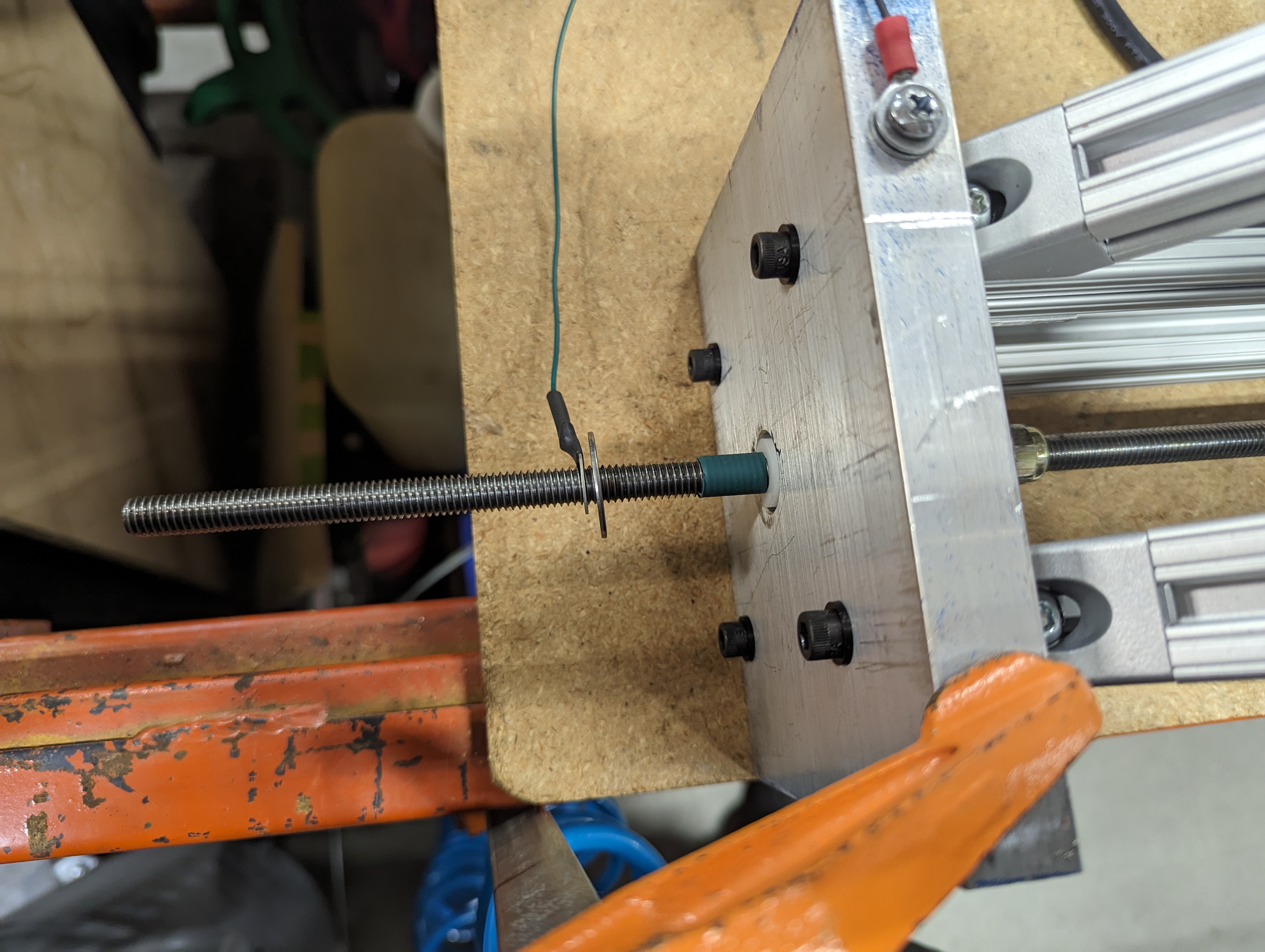
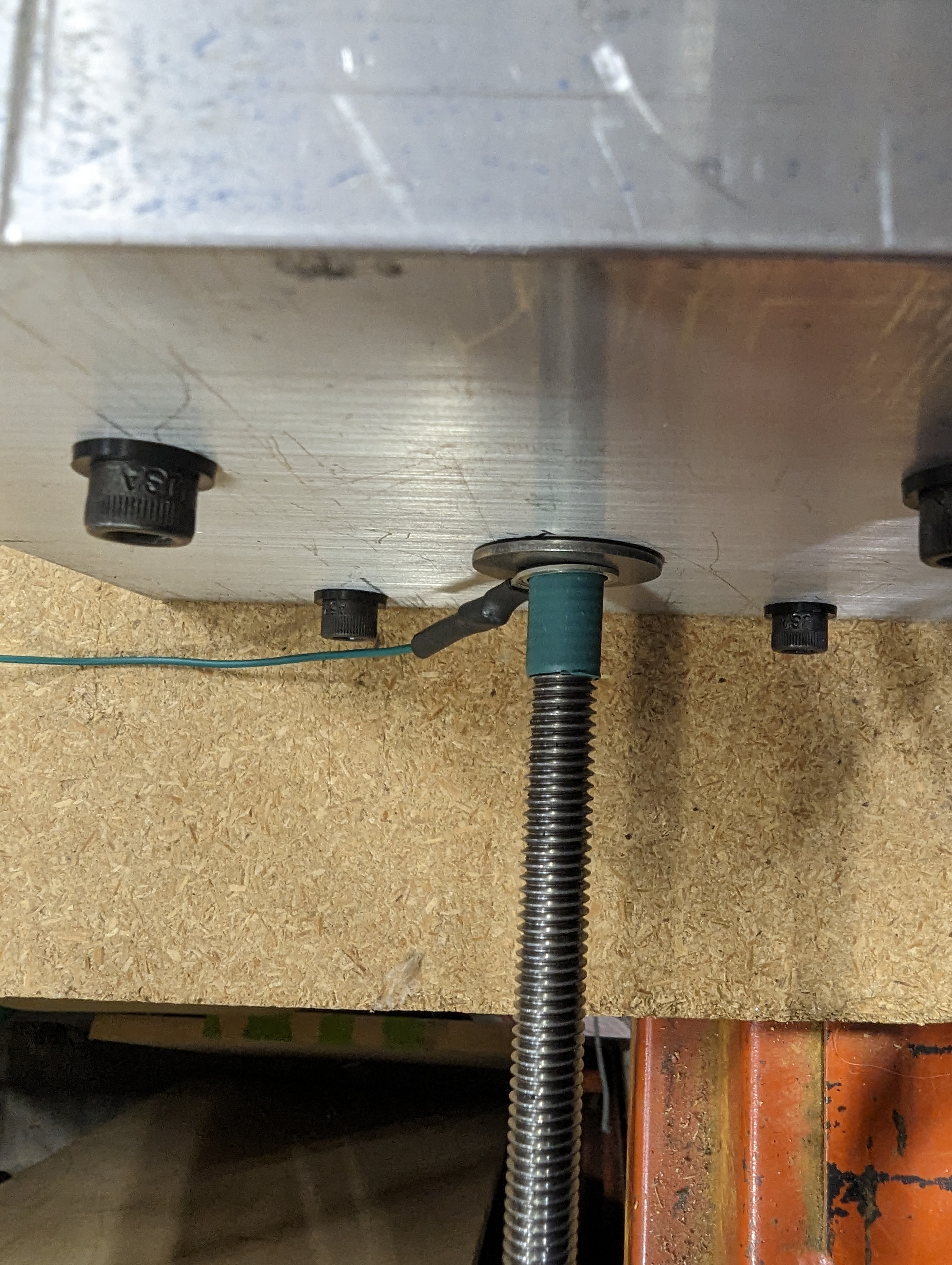
With this setup we could check which end of the stroke we were on in the software. In the photo below, the left washer is isolated from the rest of the hardware and will ground the signal pin when it touches the frame. The right washer is continuous with the entire linkage, so when the washer stack on the other side touches the frame, that will ground the other signal pin.
And with that fix, it was time to let this thing get to work! We ended up shortening the cycle a bit in order to hit our goal much faster. But now it was just time to let the machine do its thing. It was Friday when we got testing started. We knew it was pretty unlikely for the machine to still be running when we came back to the office on Monday, and we weren’t wrong!
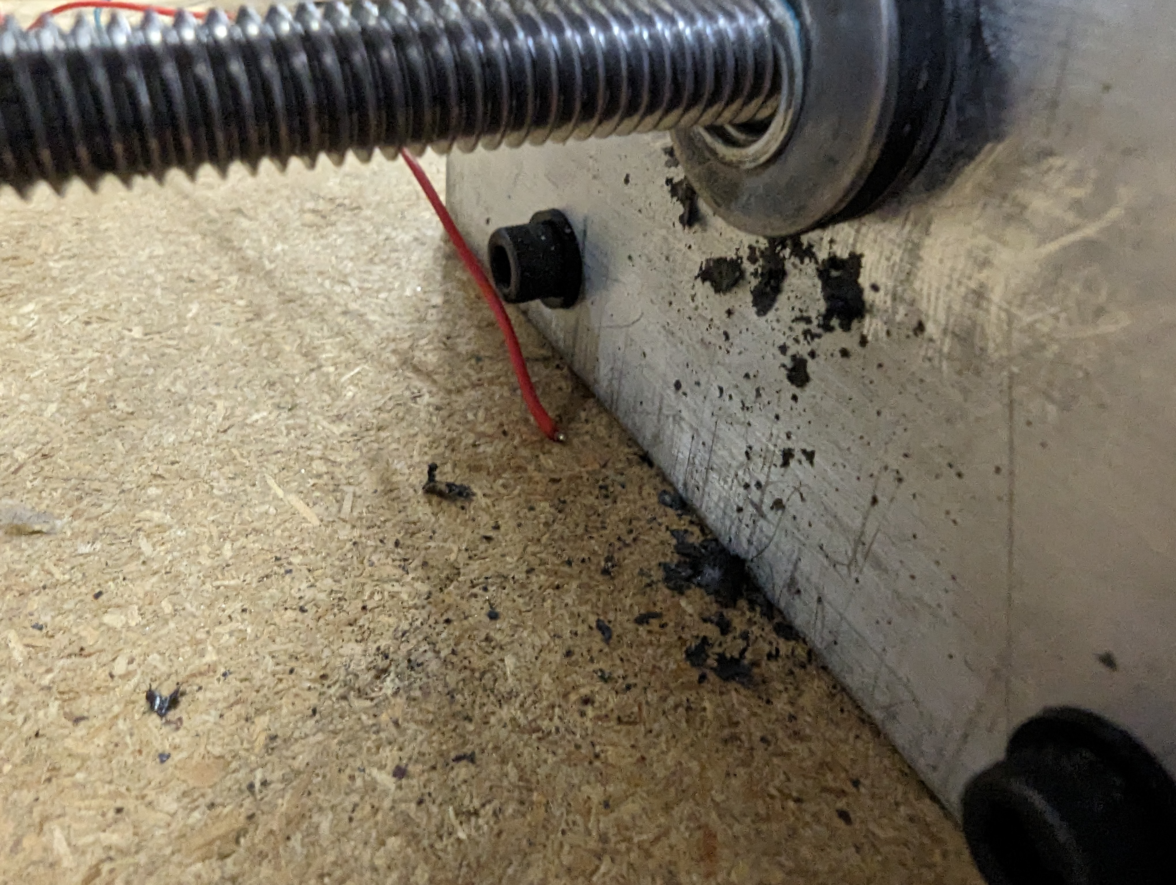
When I got back into the office on Monday the machine had completed about 260,000 cycles, but there were definitely some problems that needed to be addressed. The first was quite obvious! It was abundantly clear that the grommet was very much incompatible with the grease that we had used. This issue iltimately does not stop the machine from functioning and we didn’t have an easy alternative solution, so I just cleaned everything up and used a different grease.
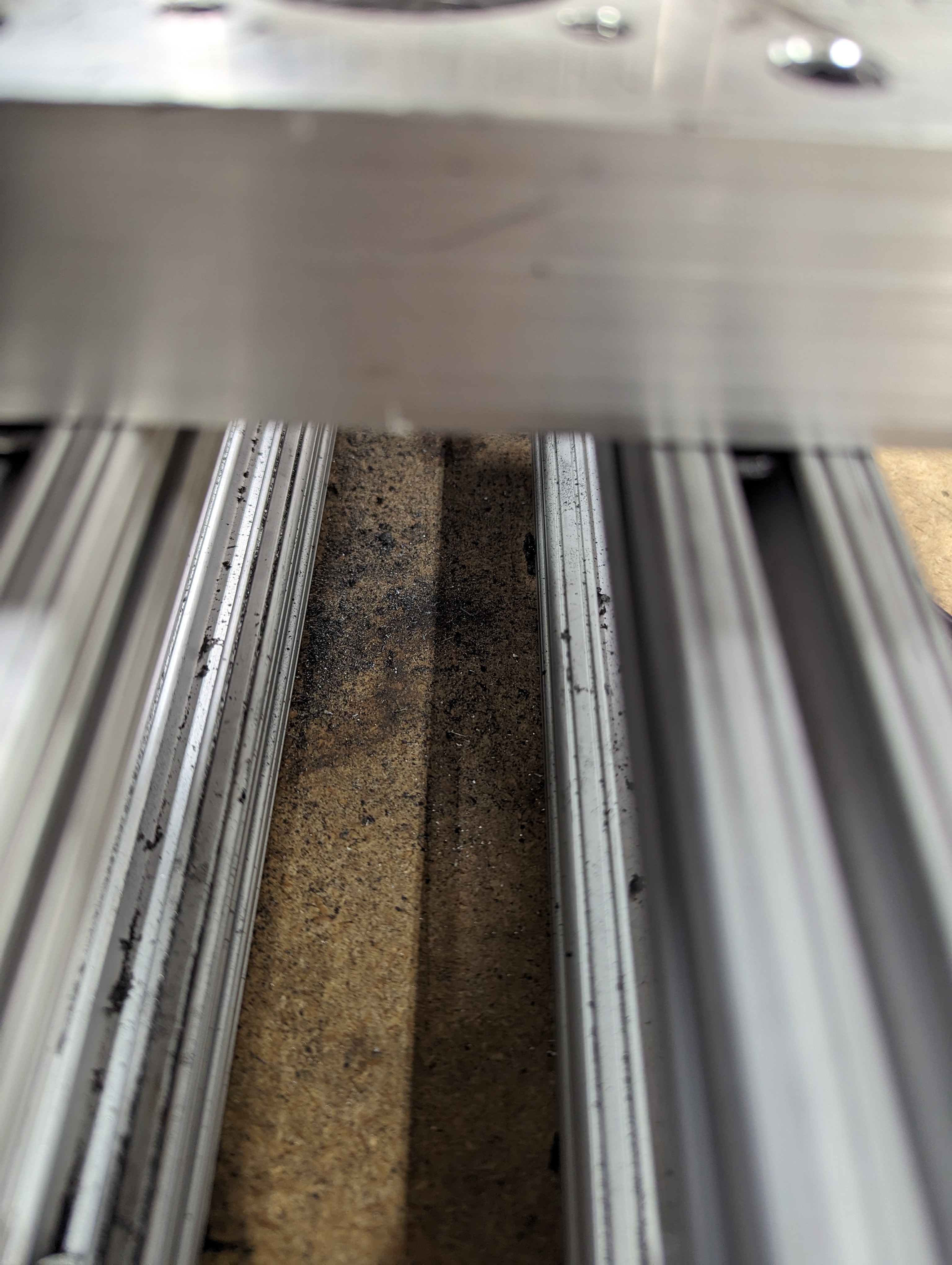
Another issue was a suspiciously high amount of metal dust around the shifter end of the linkage. It would appear that the bolt was making some extra room for itself. You can see in the video below that the hole in the bracket was now more of a slot. This was another problem that had little effect on the machine running so the solution here was to simply tighten the bolt more.
One of two major problems in this first batch of troubles was something that could trigger an error, but ultimately was not something we ended up fixing, it just became a maintenance item. As the acetal bushings at the stopper end wear they create a fine powder. This powder can build up on the frame and in some cases they actually prevent conductivity between the frame and the stop. We just made sure to give these areas a light brushing from time to time. The second of the two major problems that could cause the machine to stop is also visible. The connection between the wire and the ring terminal was fragile as these terminals are meant for much larger gauge wire. After a few iterations, I came up with a method of attaching the wire to the terminal that was much more robust.
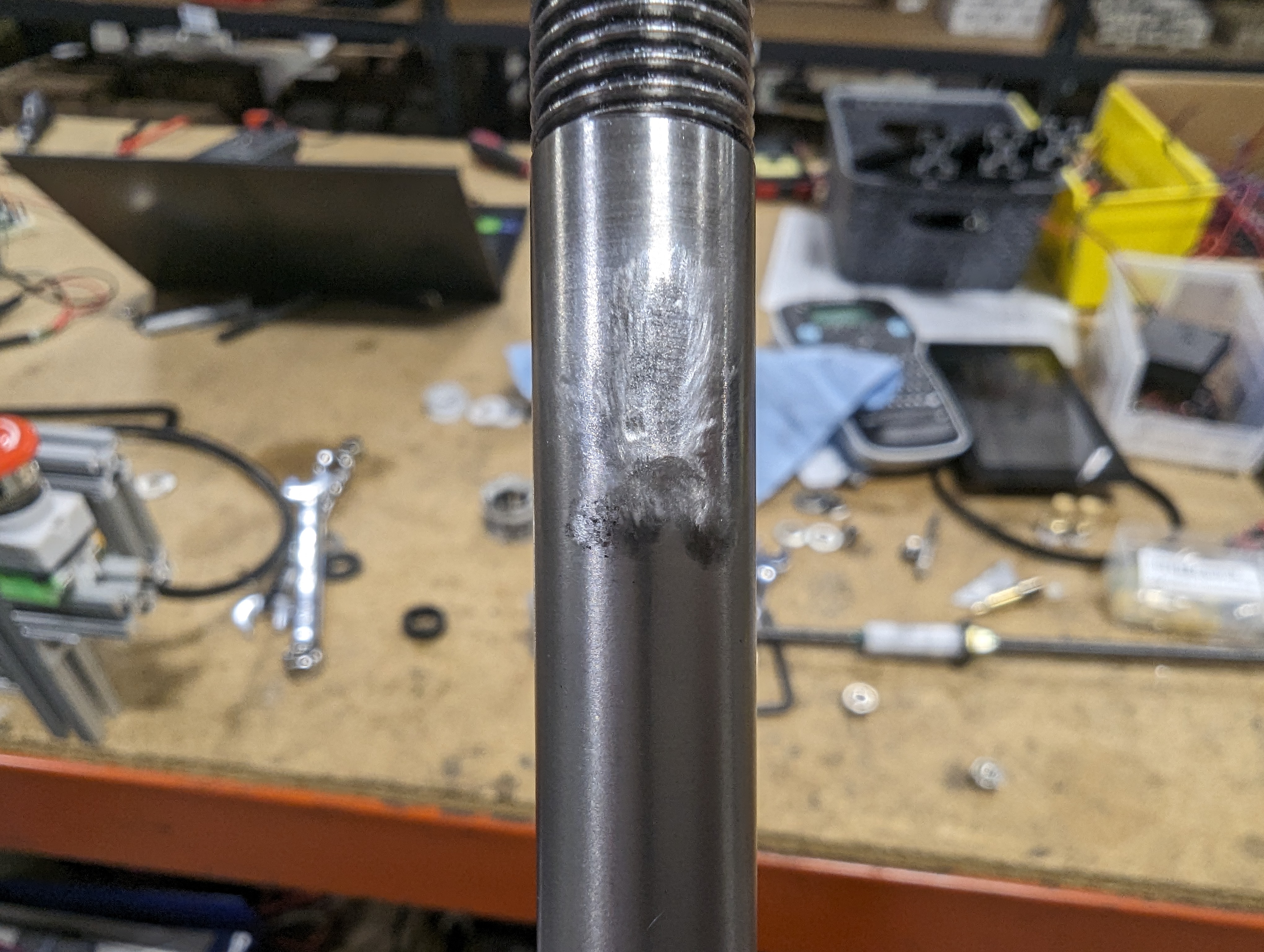
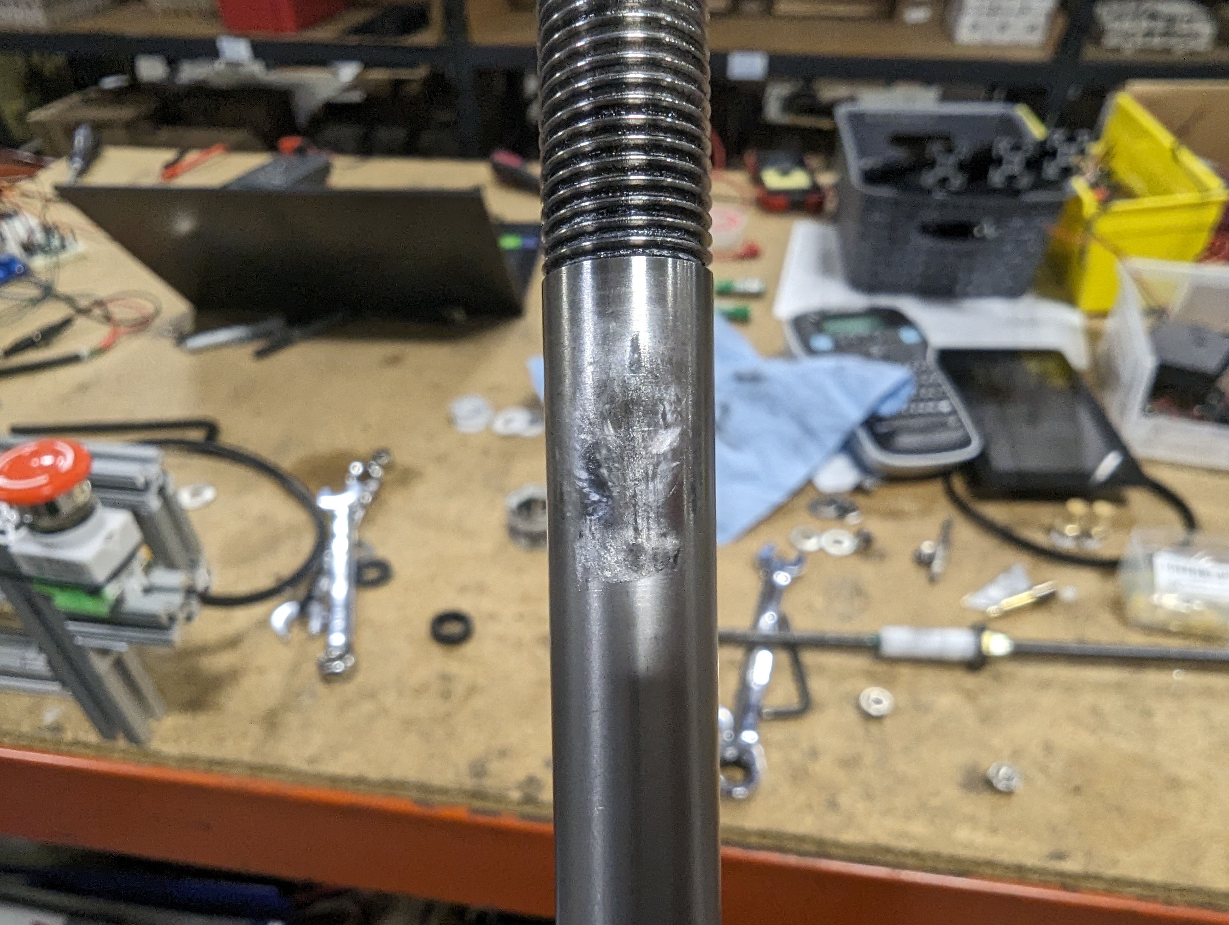
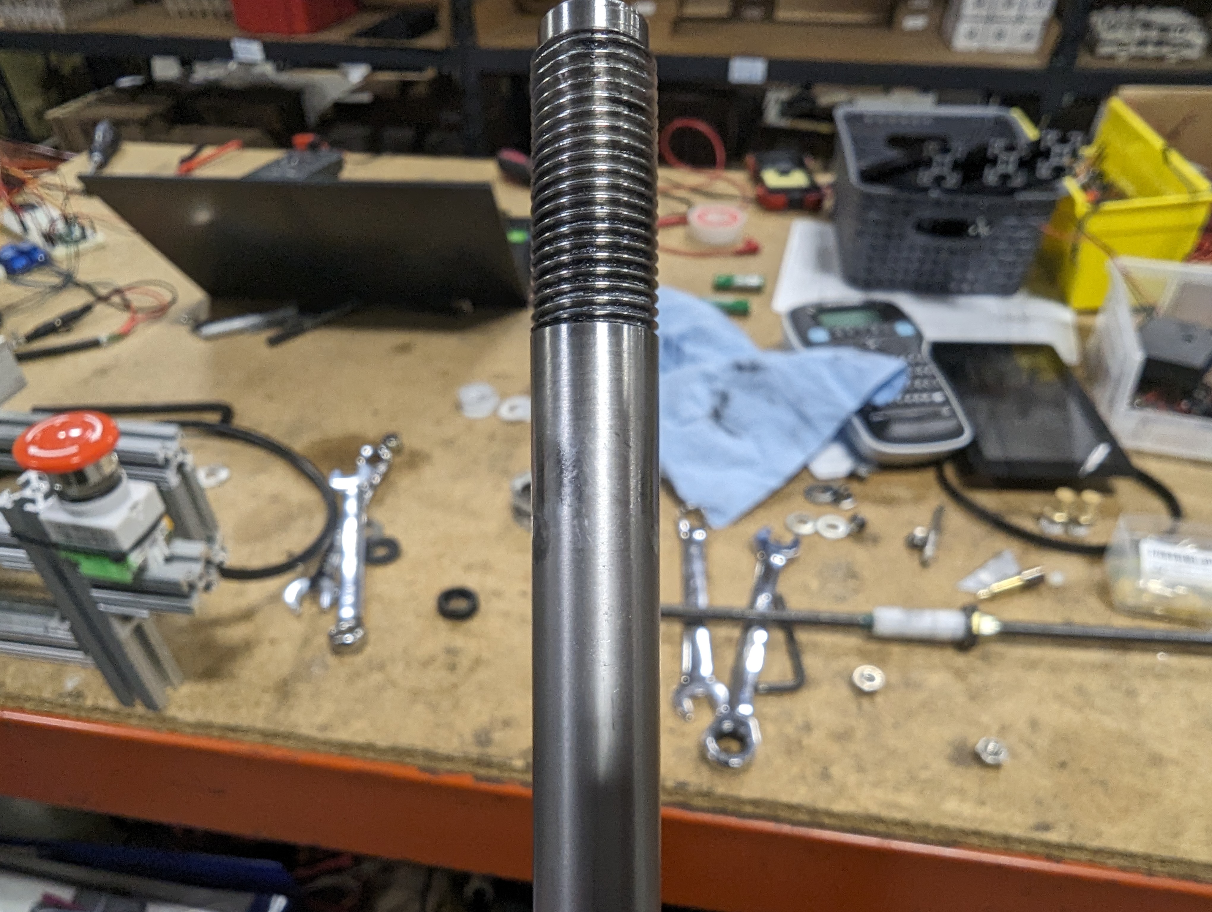
We now had the issues mostly ironed out, and with the machine running smoothly we quickly reached 1,000,000 cycles on that Friday, the 16th day of building and running the machine. Over this time we replaced the grommet several times, but never found a lubricant we had on hand that wouldn’t melt it. This led to some light wear on the shifter shaft and on the end link as once the grommet was worn out we the shaft and endlink would make contact with each other, but it was nothing that would prevent the machine from continuing on… should we be so inclined.
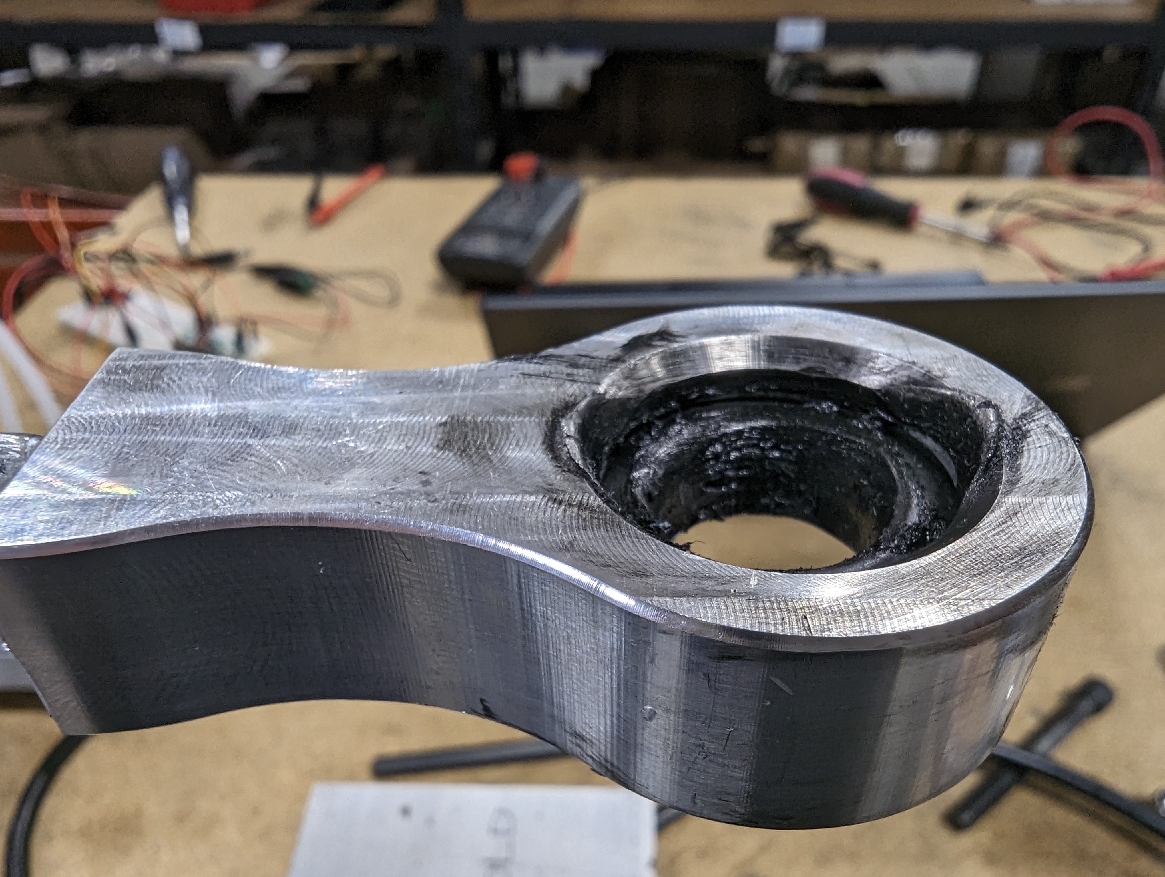
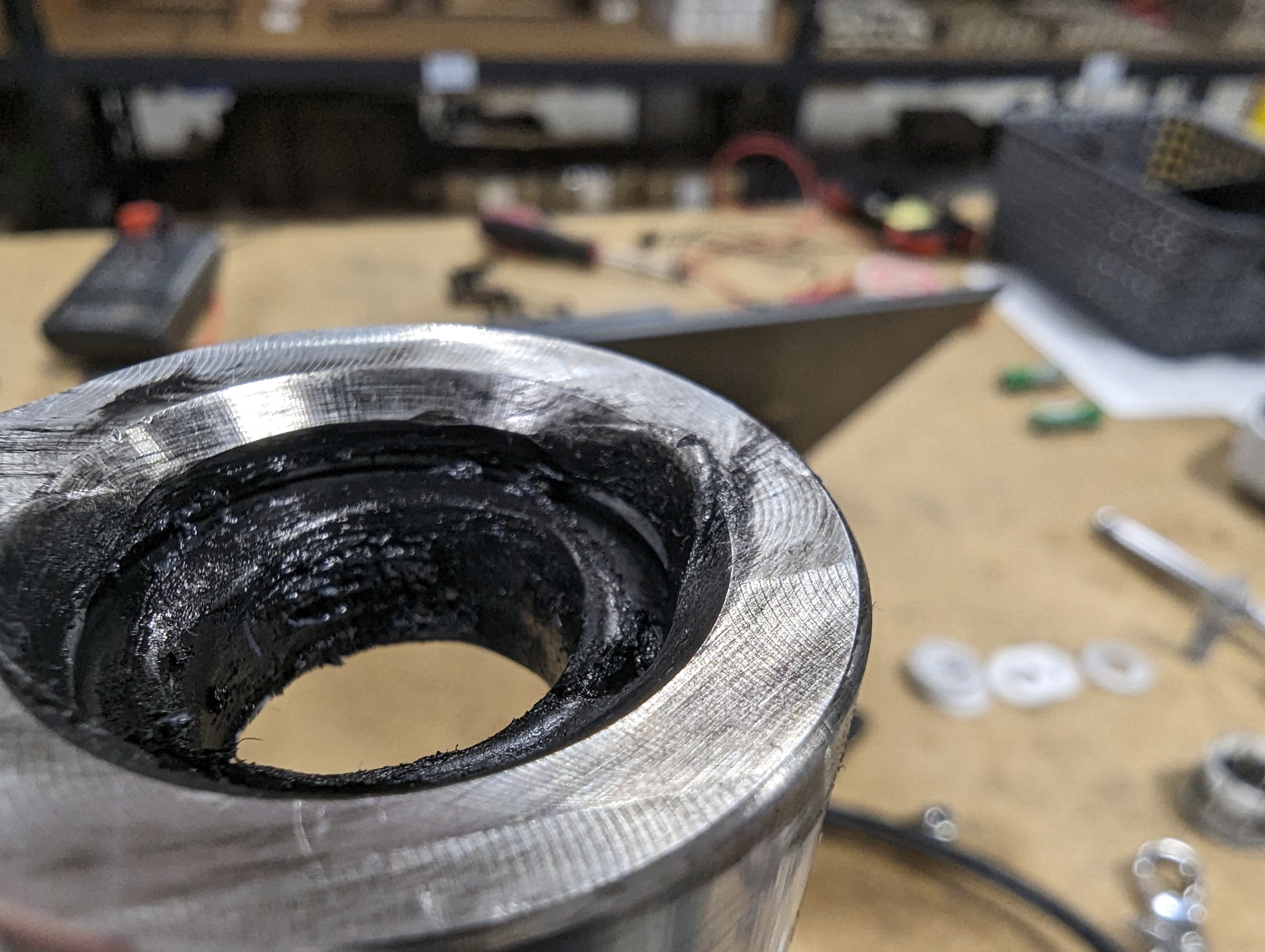
The shifter looked great. 1,000,000 cycles had zero effect on the functionality of the shifter. The assembly was completely intact with none of the hardware comming loose and no play in any of the joints. There were two areas with noticeable wear which was cause by the issues with the grommet. Once the grommet fails, we have metal on metal contact between the shifter shaft and the end link.
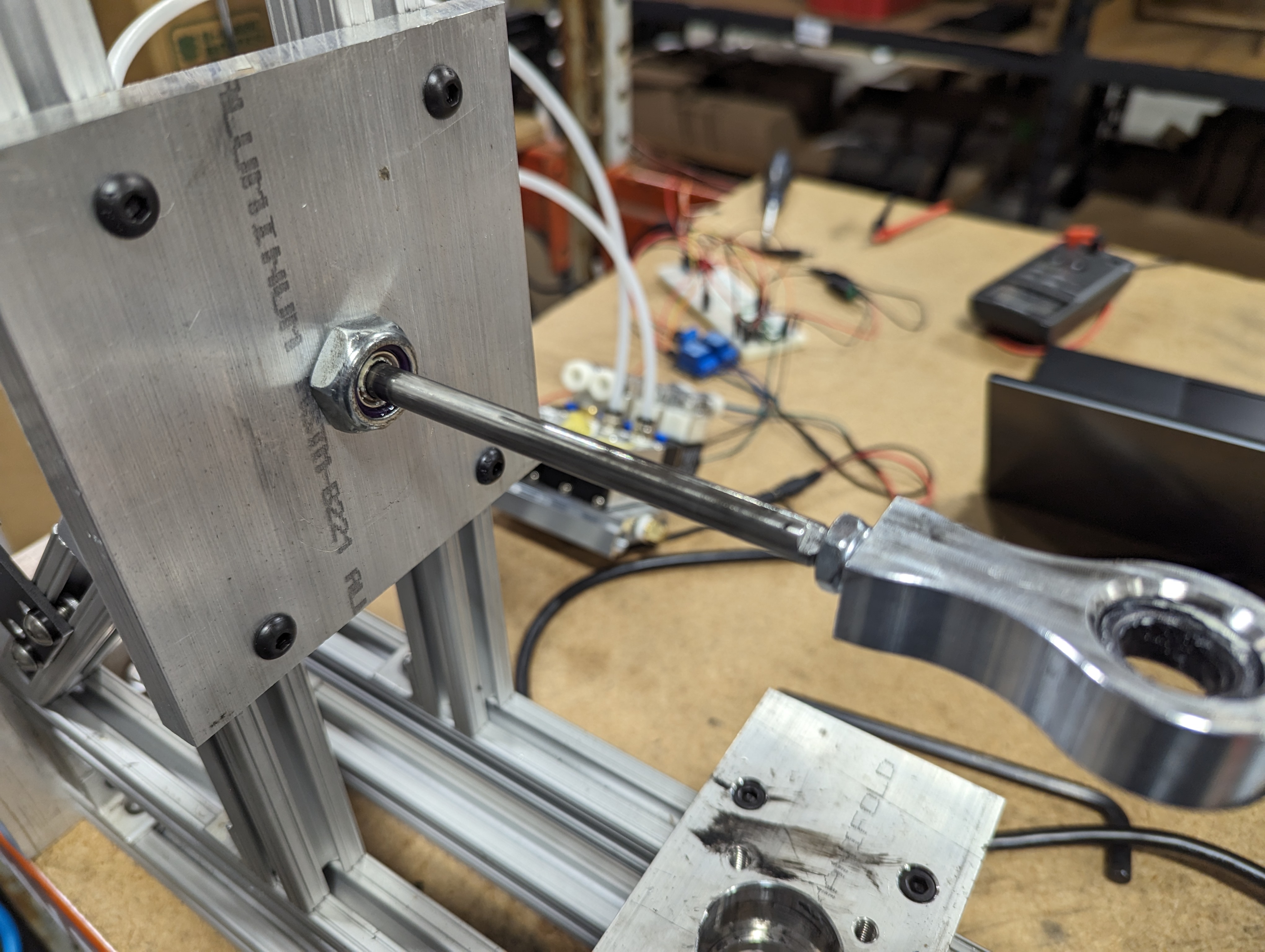
The machine itself was doing alright and just needed a little cleaning up. Definitely some noticeable wear, but nothing that would stop it from working. The damage from the grommet failures was fairly obvious.

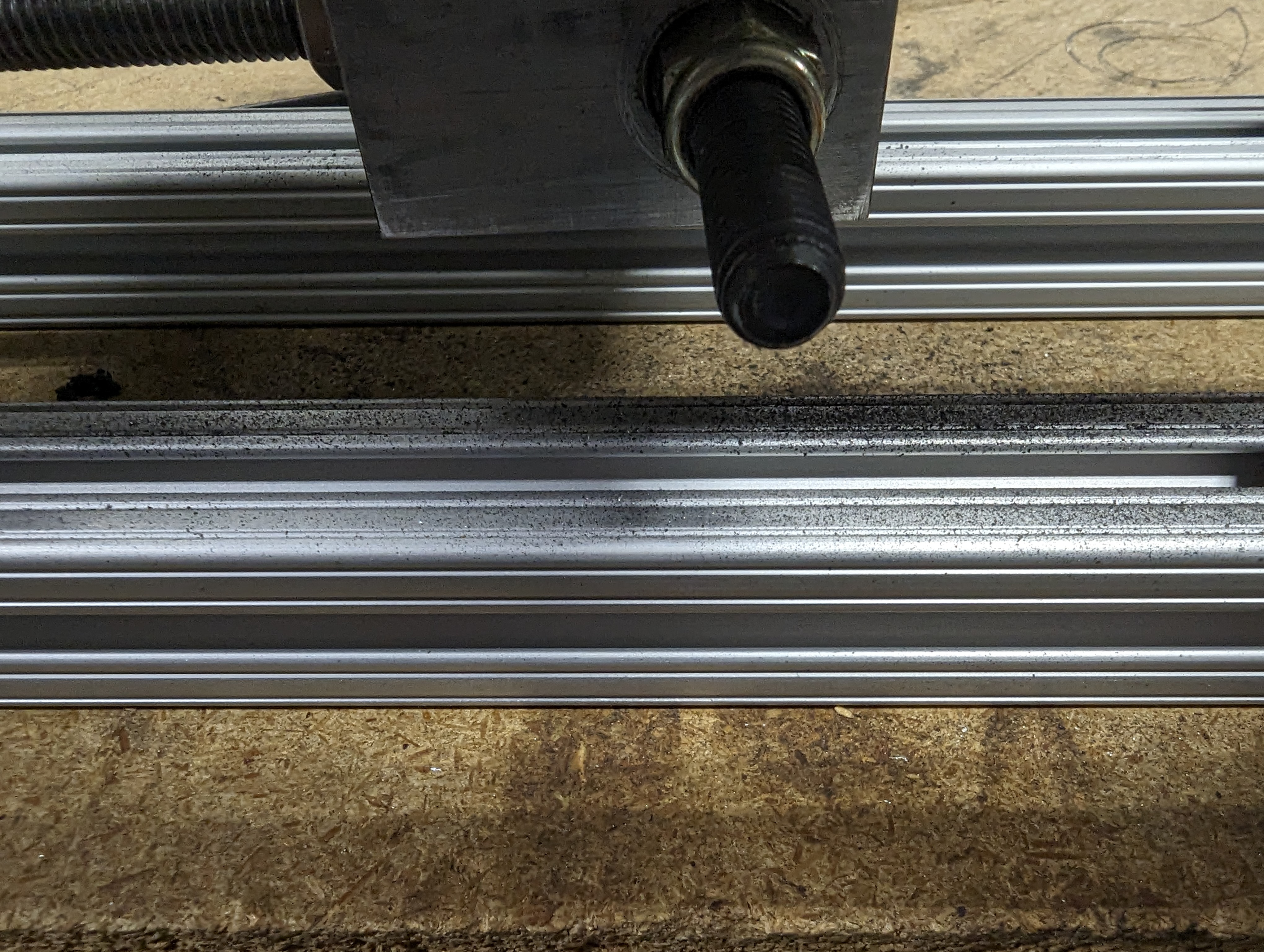
The piston shaft had developed a slight bend. If you noticed in the videos, when the piston reaches the end of the travel but is still pushing on the shifter, the shaft is deflected upwards as the greased grommet allows it to climb up the shaft. We wanted to avoid this, but no lubrication would result in much more frequent grommet changes. The bend could be felt if you actuated the piston buy hand. But it still worked, so we cleaned it up the best we could and moved on.
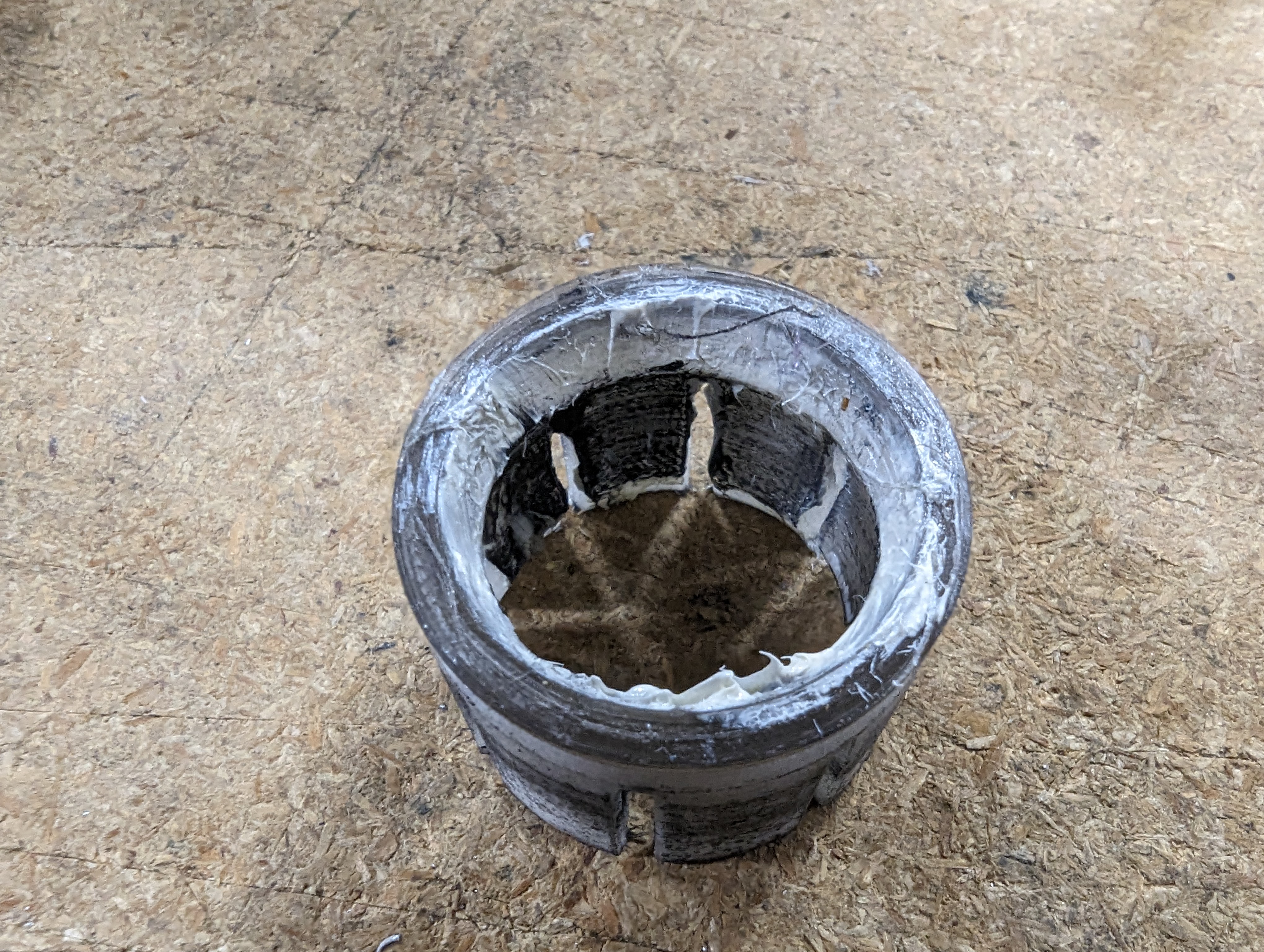
The shifter block was in fine shape, just a little dirty from having bits of melting rubber rained down on it. With an abrasive mixed into the grease for the pivot, we did get some wear in the nylon retaining clip.
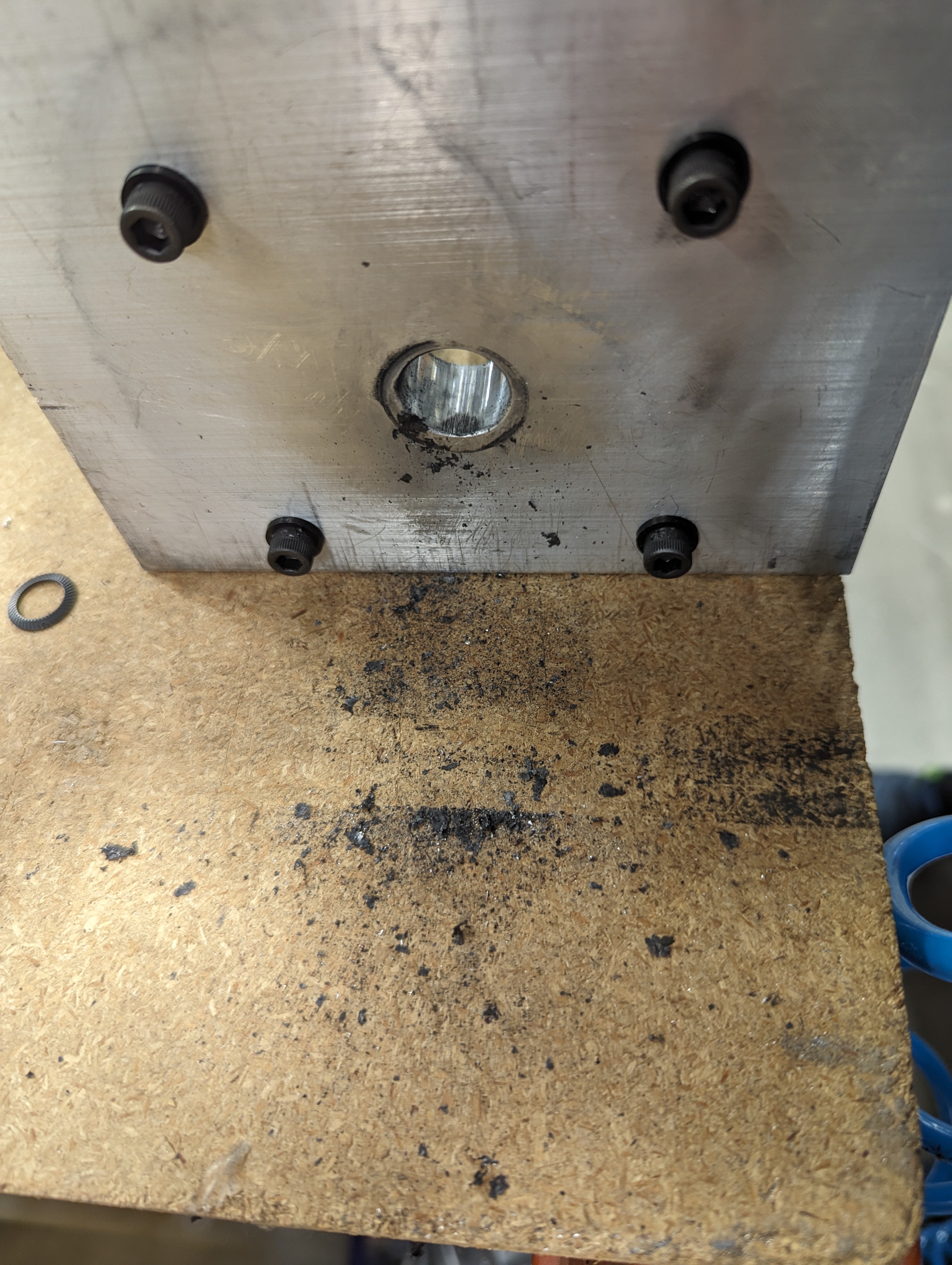
There was quite a lot of dust and bits of decaying grommet building up under the machine.
Both of the acetal bushings showed some wear but were otherwise fine.
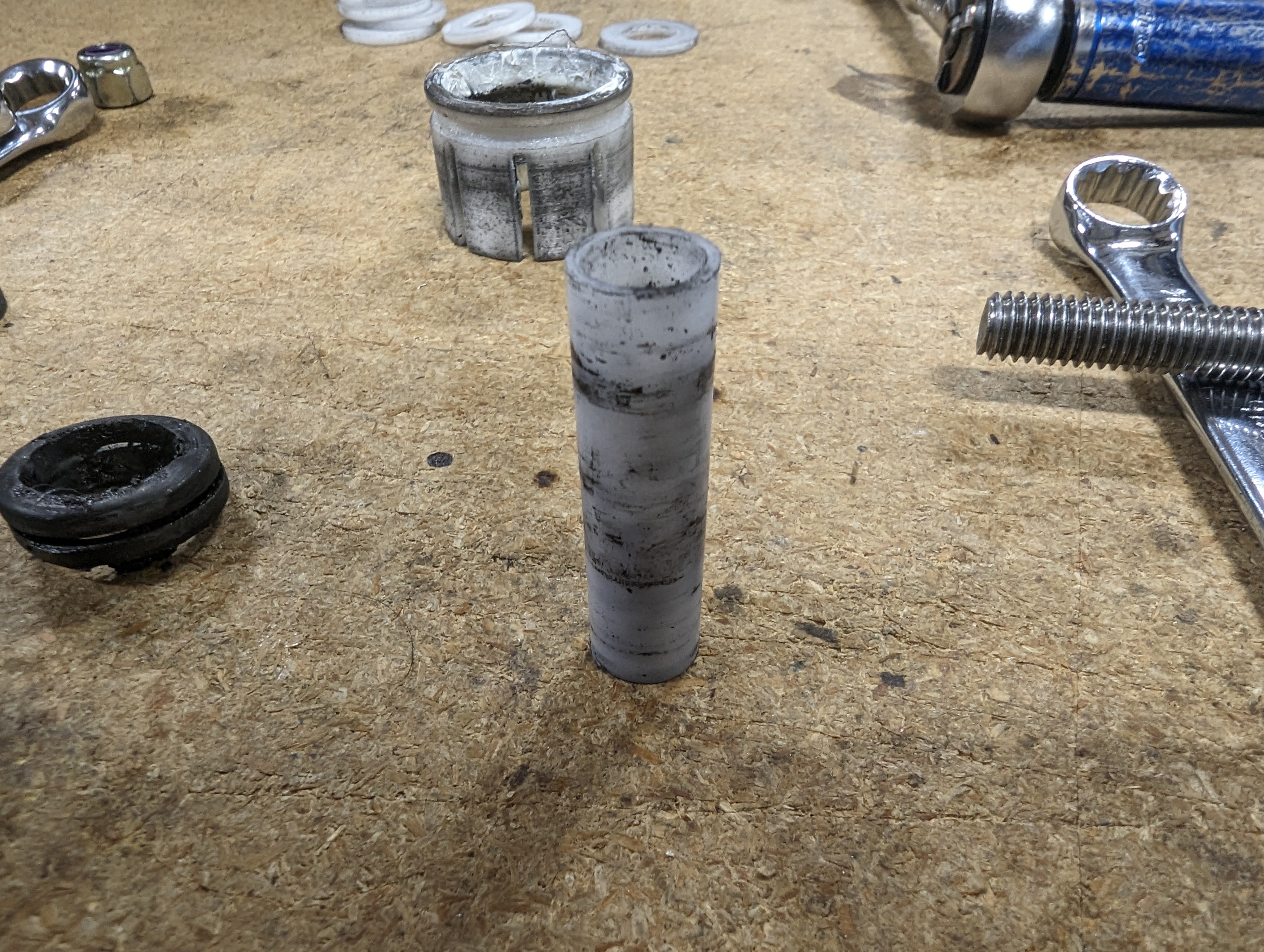
The aluminum bracket that helped connect the all thread to the shifter saw the most damage. We pegged this to be the first part that would fail, and while it would eventually fail, it hadn’t yet. All of the hardware on this end was ready to be put back into service.
You might have picked up by now that we are not done with this machine. The way everything looked, we felt our little shifter had the strength to go well beyond anything like it would actually experience in the real world, and we were very interested in finding out if we were right. We decided to run another 1,000,000 cycles, but this time we would up the pressure substantially.
We decided to turn the regulator up to about 60 psi, which should translate to about 55 lbs of force on each shift. Now, if you are ever putting that much force into a shift, something has gone horribly wrong, but we were very excited to find out just how strong it was. With the machine running, it was immediately noticeable that this pressure was a different ball game. You could now see the entire frame flexing on each shift.
And so with the pressure cranked we set the shifternator lose for another weekend of shifting fun!
That will conclude part one of this 3 part deep dive into our shifter testing adventure. Next time we'll take a look at some of the damage caused (to the machine) by this very overkill 2nd round of testing. Then we'll get into the final phase of testing and all the results we received that have lead to the re-release of the GR86 shifter which is available now!