Solid Shifting in the MINI
Posted by Jacob on 16th May 2019

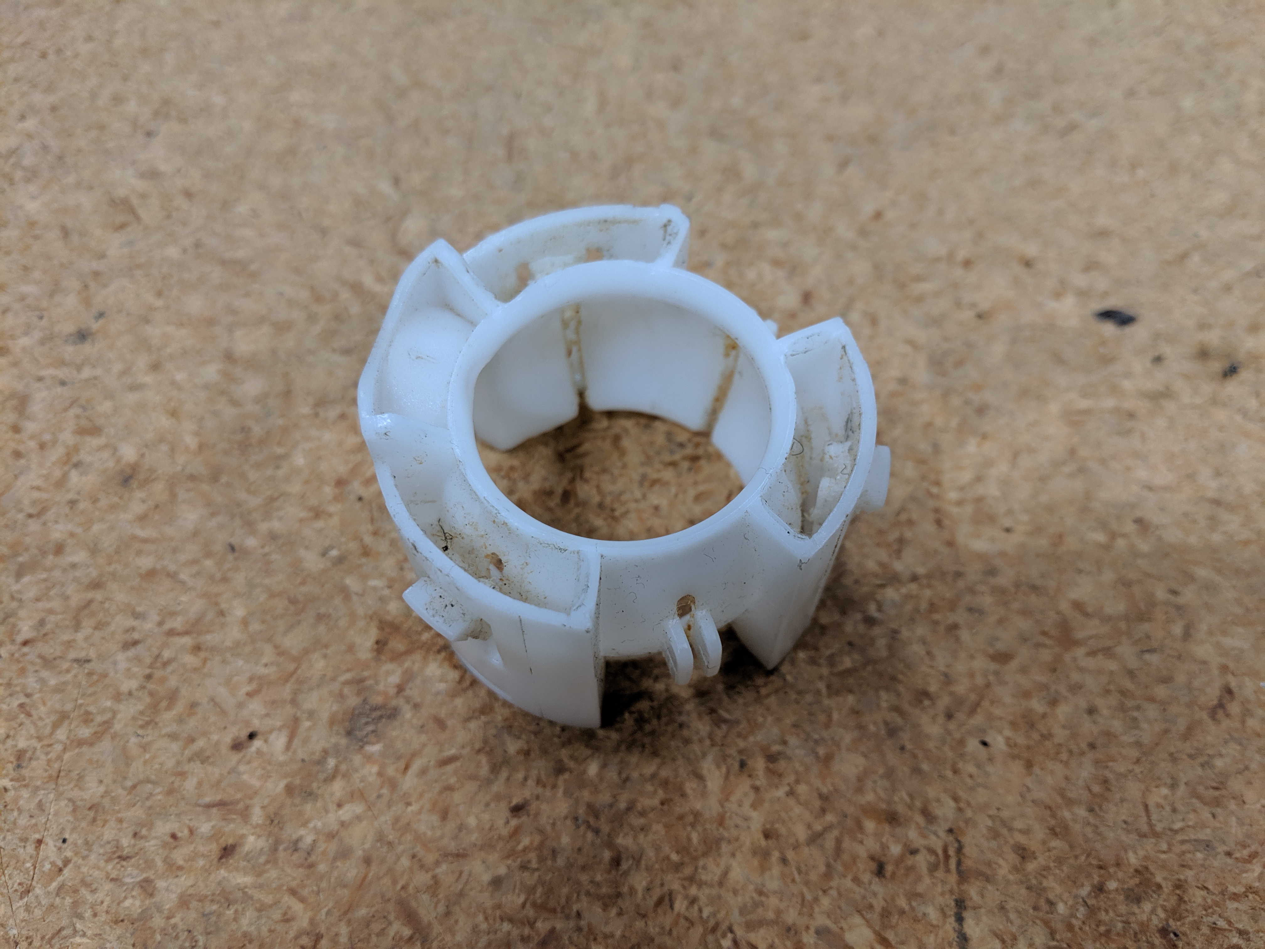
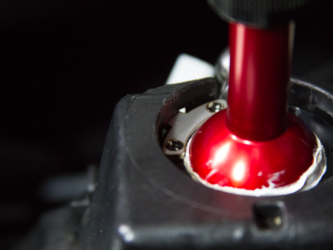
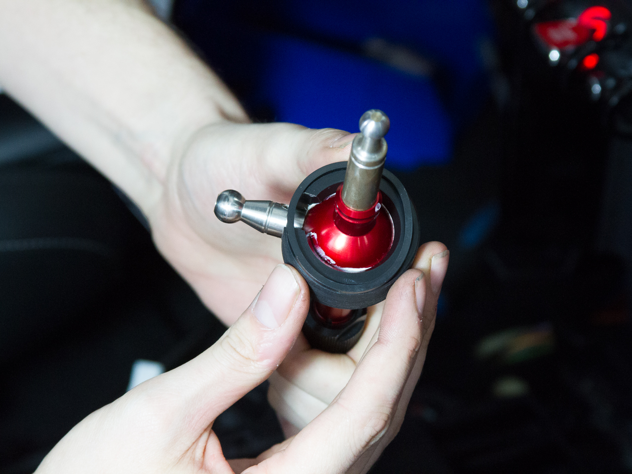
If you’ve bought one of our short shifters, or ever had to do any work on the OEM shifter, you know how ridiculously difficult it is to get the retainer clip out of the housing. Even with half a dozen flat-blade screwdrivers and an extra person to help you, there’s a good chance that clip isn’t going to make it out of there in one piece.
This was an issue we needed to address very early on in our short shifter process, as the default solutions were either spend $600 to purchase the entire housing assembly from MINI, or just beg and plead with the automotive gods that yours didn’t break when you took it out.
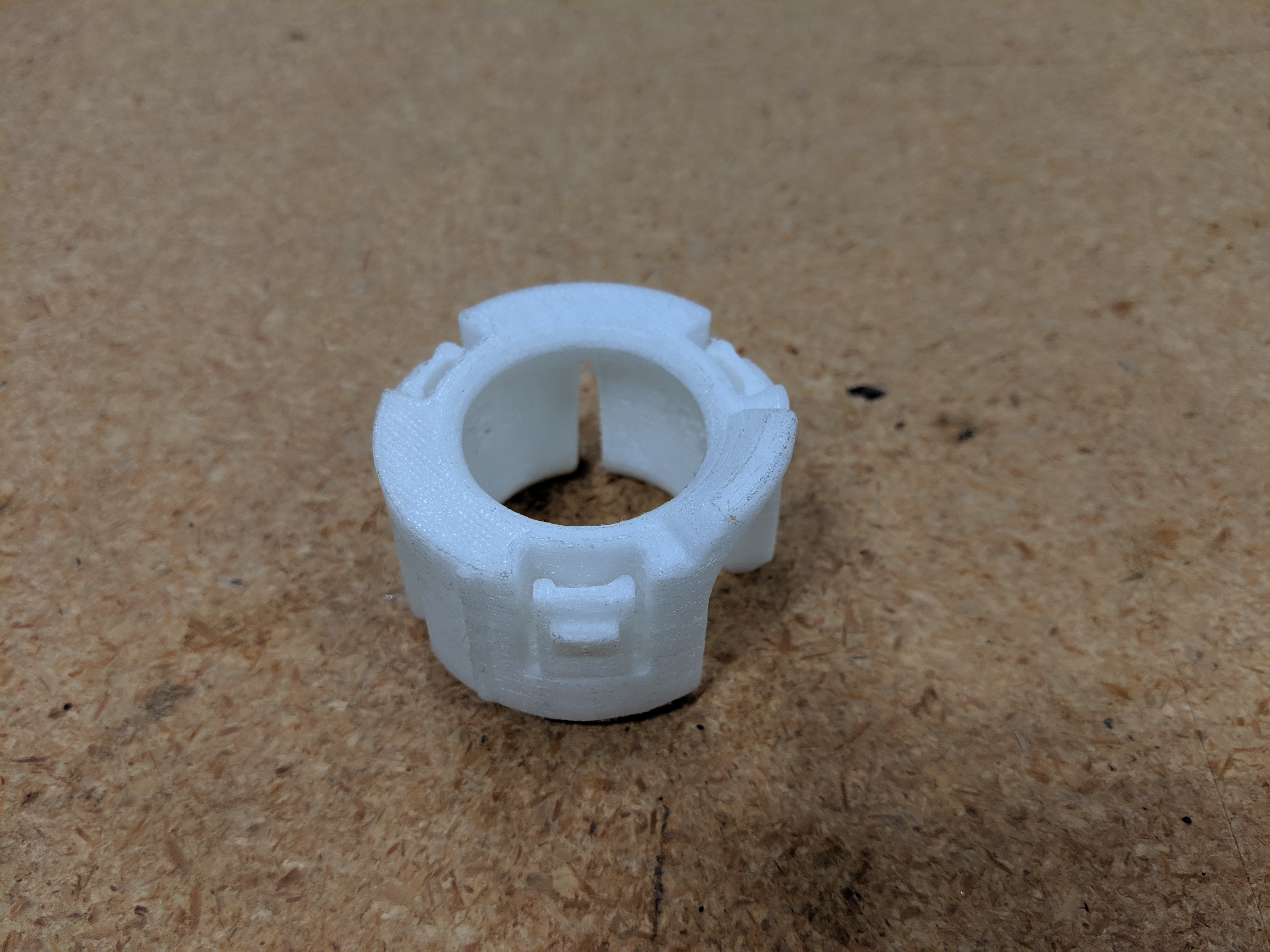
Our first major breakthrough was the availability of 3D printing. Once we had an FDM printer on our desk, we could make our own replacement clips out of nylon. While it was a pain to hand finish all of these, they worked surprisingly well, and even tightened up the shifter feel a little bit.
The problem with printing plastic pieces from filament is that the bonds between the layers aren’t as durable as we’d like them to be. After a few hot summers and cold winters, thermal expansion began to take its toll. While well suited to the everyday abuse of a commute or even a spirited weekend drive, our printed part will eventually become not as smooth or crisp as we would like it to be.
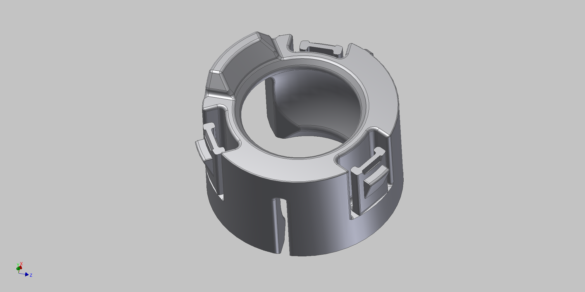
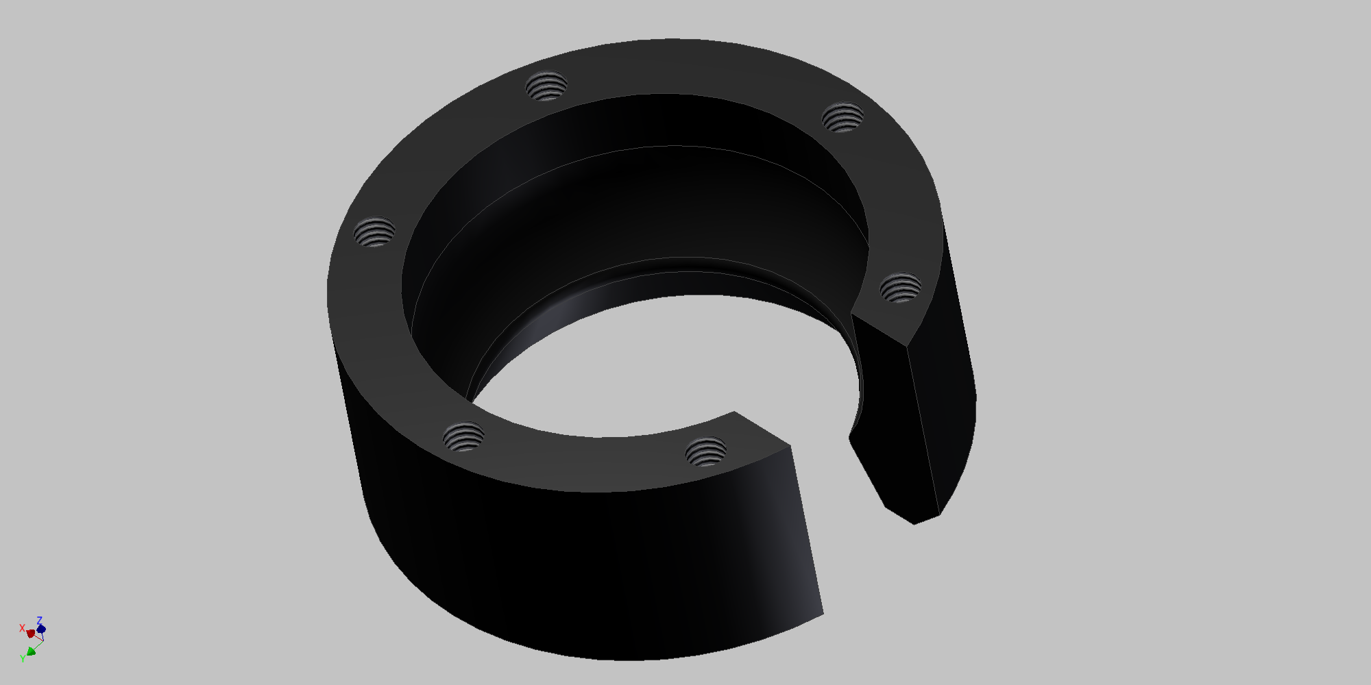
We needed an alternate solution, and there were brief discussions of having our own mold made in order to replicate the OEM clip. The cost to make a mold combined with our dislike for the OEM design led us to investigate a fully machined version. In our first few iterations it was clear that the best advantage (apart from it being 100% solid) is that we could make a multi-piece assembly that would be easy to install and uninstall. Next it was time to nail down material choices.

We wanted the main body to be machined out of a plastic that would have decent flexibility and wear resistance, which narrowed our choices to a few polymers. Nylon, acetal, PEEK, teflon, and HDPE all fit within that category, so we started to compare cost, tensile strength, impact toughness, and machinability.
It came down to a choice between nylon and acetal. With acetal more likely to be used in bushings, bearings, and fittings, and also a good deal easier to machine, we decided to give it a try.
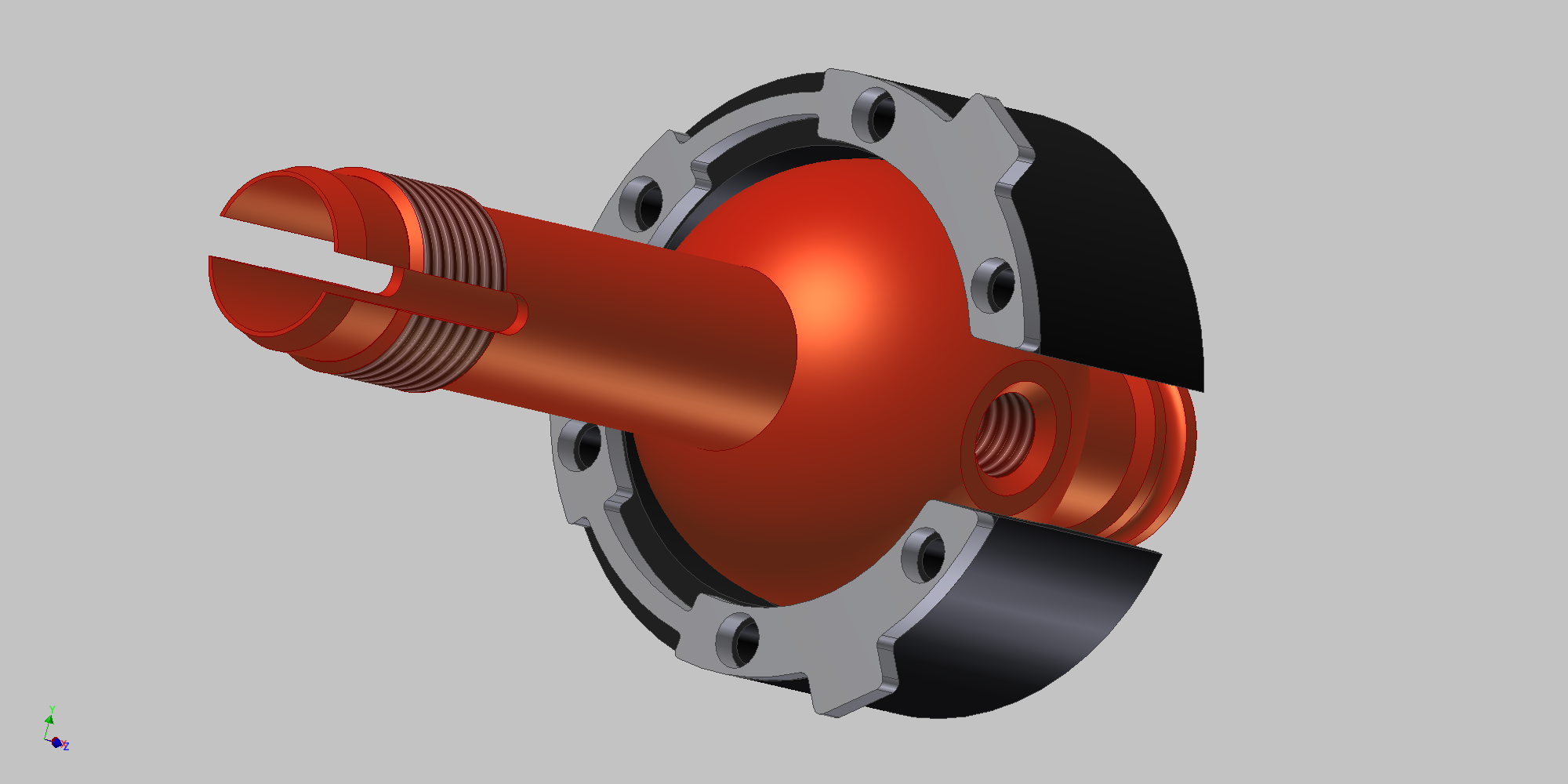
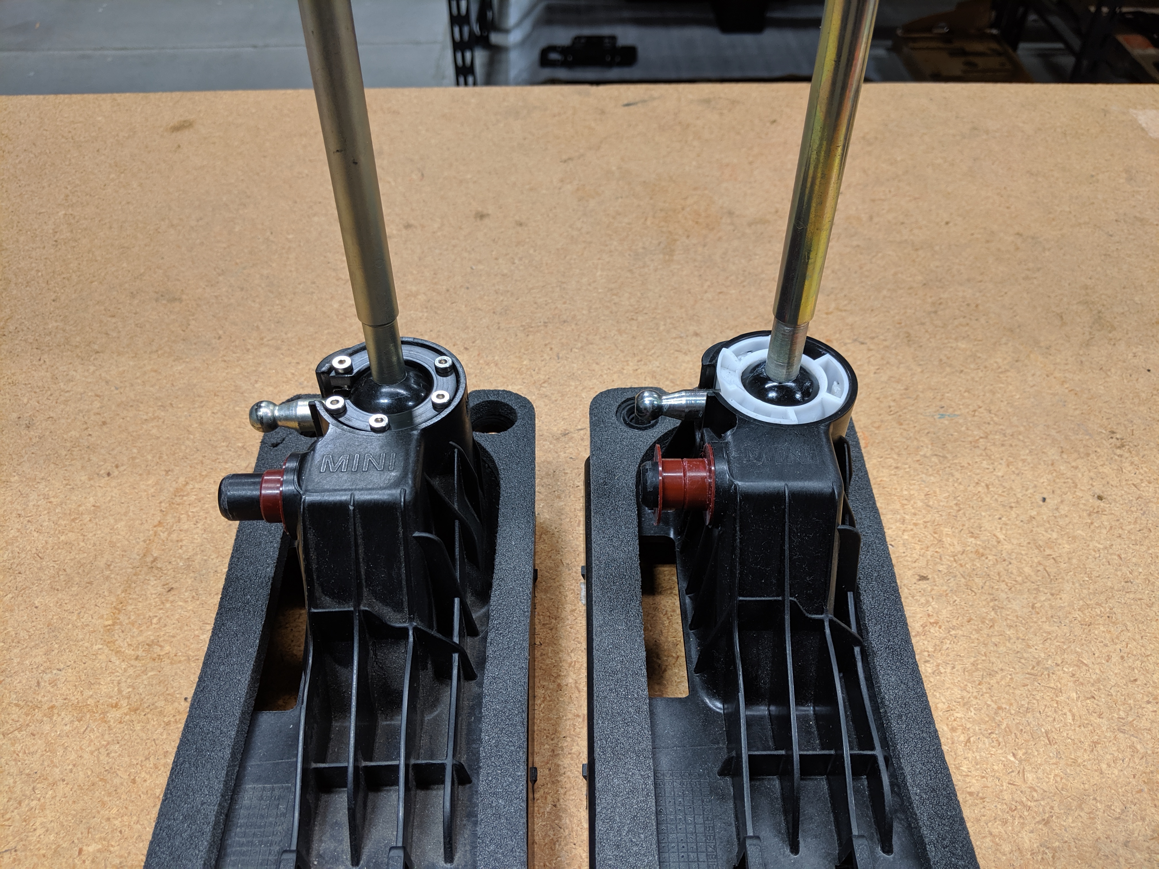
We then worked on a design for the locking mechanism. We needed to make a part with three tabs that engage these slots on the housing.
A variety of different stainless steel shapes were drawn and redrawn. It needed to secure the shifter better than OEM, but it also needed to be way less of a hassle to put in and take out. We prototyped a single piece construction that locked into all 3 slots simultaneously, but it was tricky to install and was prone to break if removed too often.
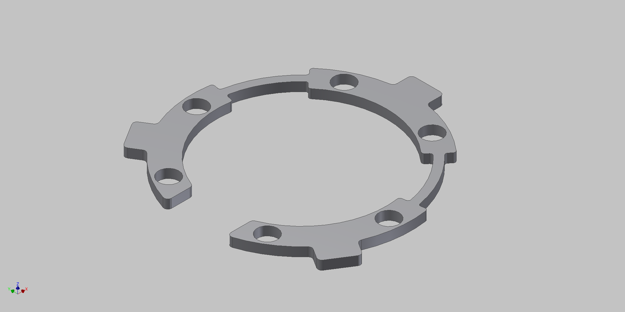
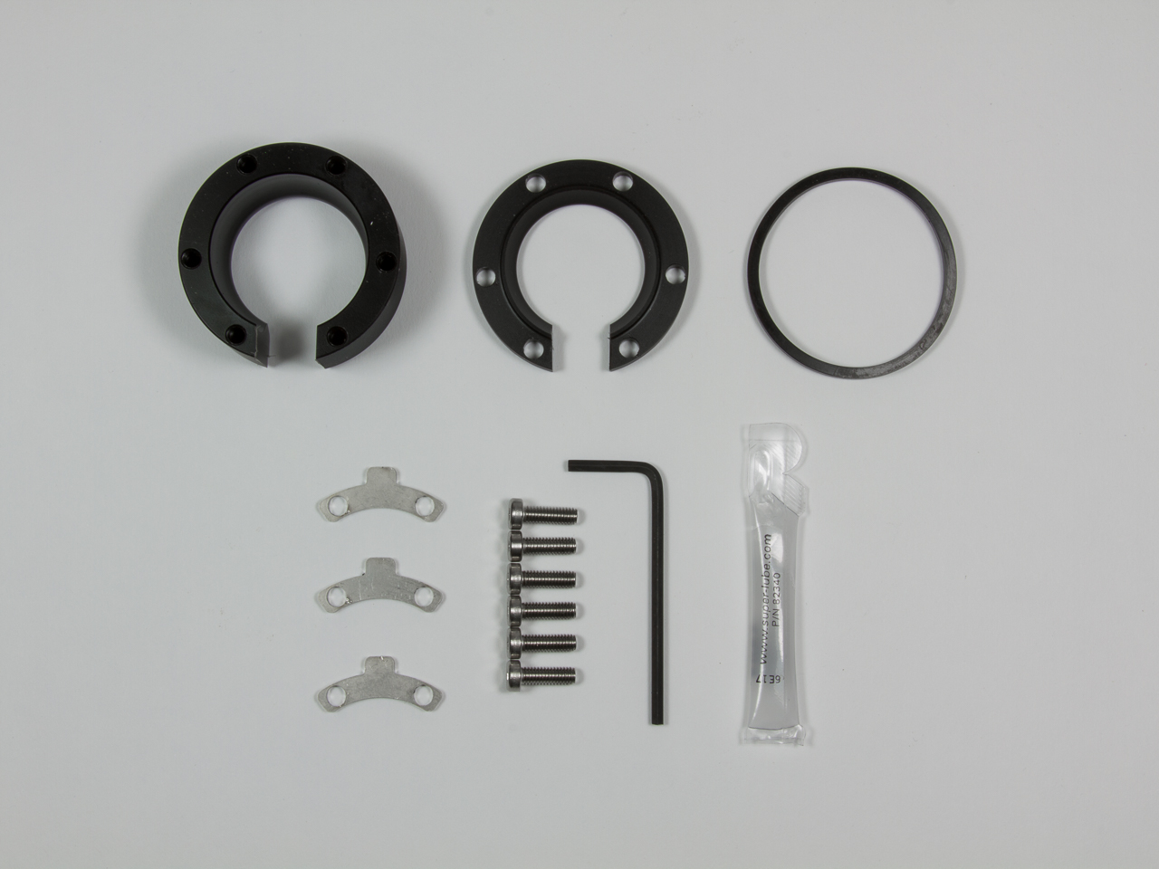
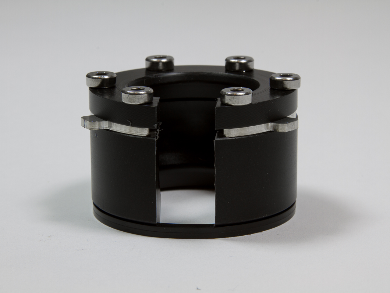
The simpler option was much more effective. We split the single piece lock into three separate pieces. With 6 bolts to hold each lock into place on both sides, the assembly was extremely secure.
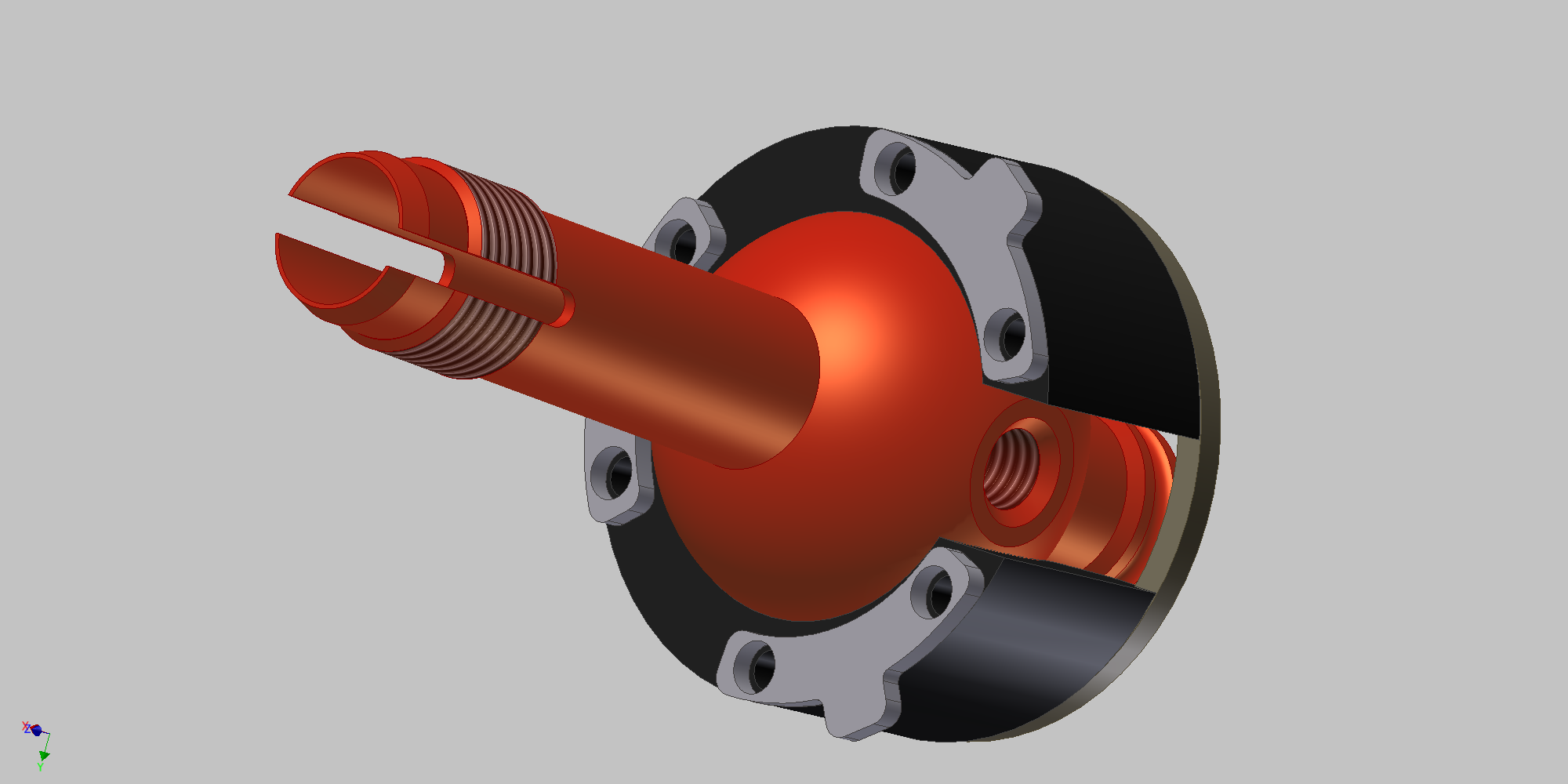
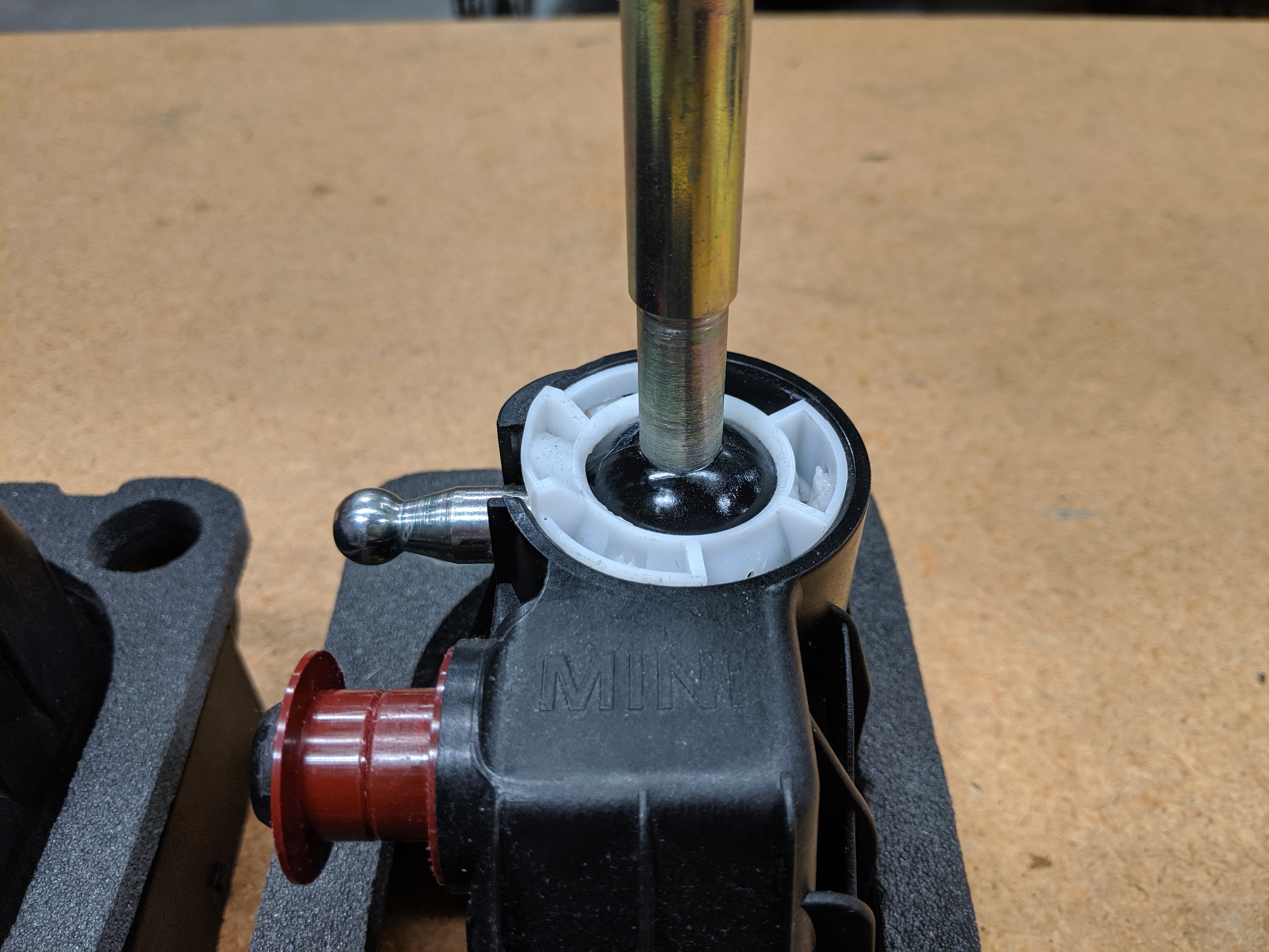
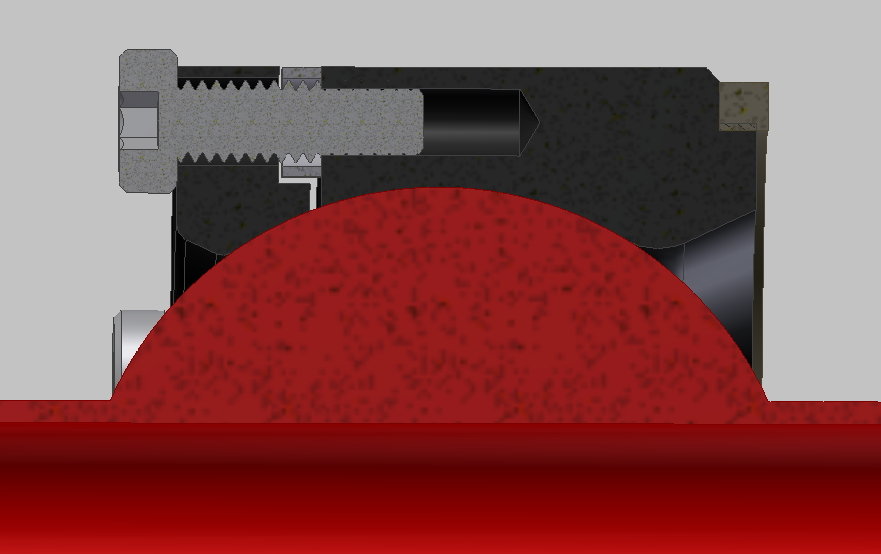
We noticed during this process is that the variation between housings cause it to rattle. Because the machining process is so much more precise than that of injection molding, and the lower clip was clamping against the main pivot, the outside profile of the lower clip would slide around inside the housing. Even a few thousandths of an inch of a gap was noticeable. The locking tabs would also bounce up and down inside the housing.
To alleviate both problems, we cut a shoulder into the bottom of the lower clip to allow for a square o-ring. This stops the lower retainer from moving around inside the housing, and also pushes the stainless locks up into the top of the slots, reducing the occurrence of any unwanted noise.
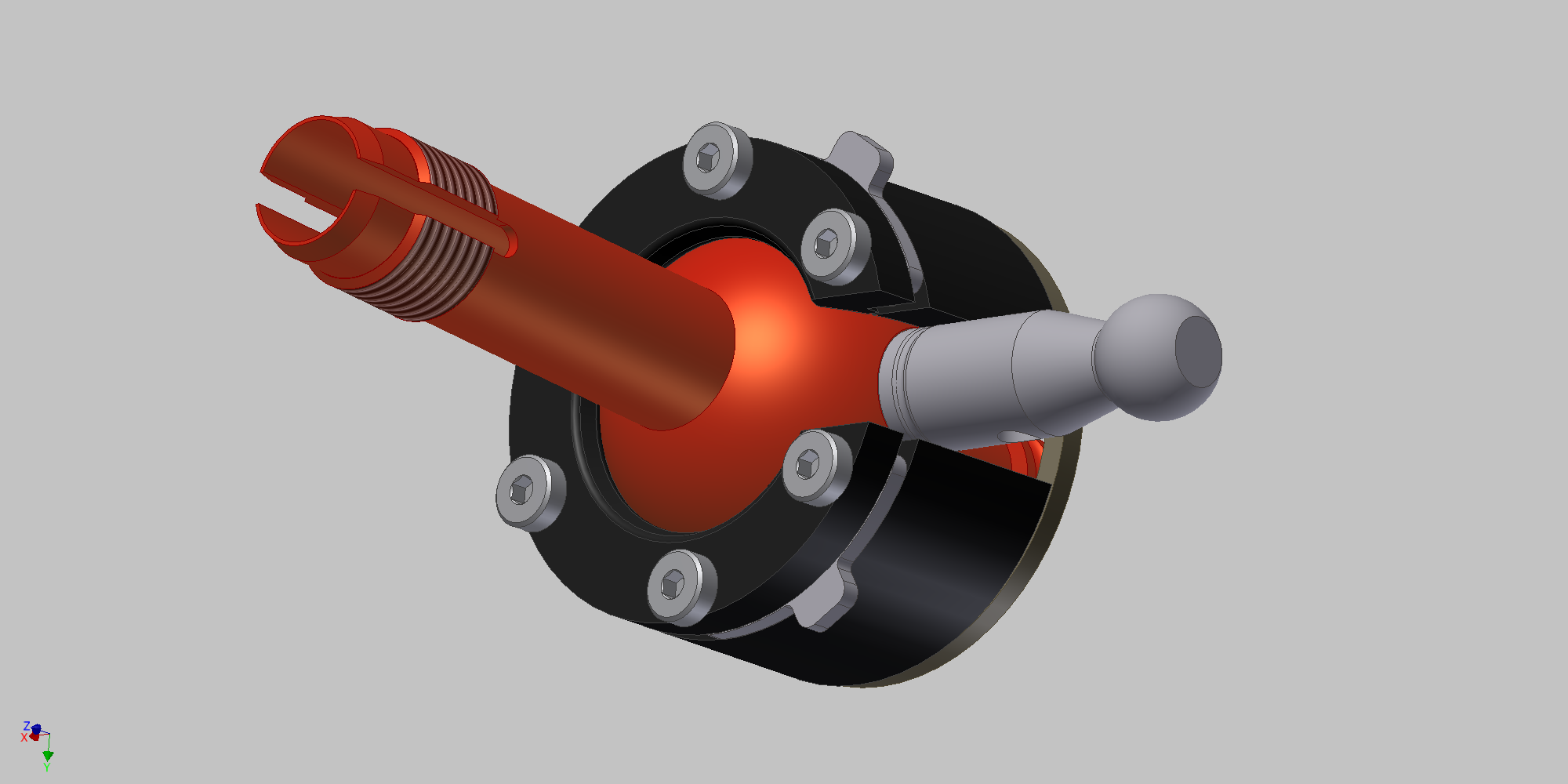
When determining how to fasten everything together, we discovered that there wasn't a wide variety of options. We needed to use the largest bolts possible for strength, and found that low profile socket head M4x0.7 screws fit best. Unfortunately because of the size of the heads, the assembly won't fit down into the deeper housing found in the R53.
Designing the top piece was a really fun way to put a bow on this project. By creating an oversized clearance slot for the locks on the top ring, we give users the ability to adjust the shifter feel. It all comes down to how you tighten the bolts. Lightly snug will emulate the shifter feel you get with the OE clip.
Applying a bit more torque to the six low-profile socket heads will tighten up the neutral return action on the shifter, and reduce some of the noise that the linkage makes. The threaded holes in the acetal lower clip are naturally undersize, and the slightly elastic nature of the polymer will prevent the stainless hardware from backing out or coming loose.
All of this comes together to be the perfect way to fix your broken clip problem and smooth out your shifting.