THANK YOU for purchasing the MINI Gen 2 Complete Gauge Pod Kit from CravenSpeed. This product is made from the highest grade materials, and is guaranteed to be free from defects.
You can buy our CravenSpeed Complete Gauge Pod Kit for MINI Gen 2 here
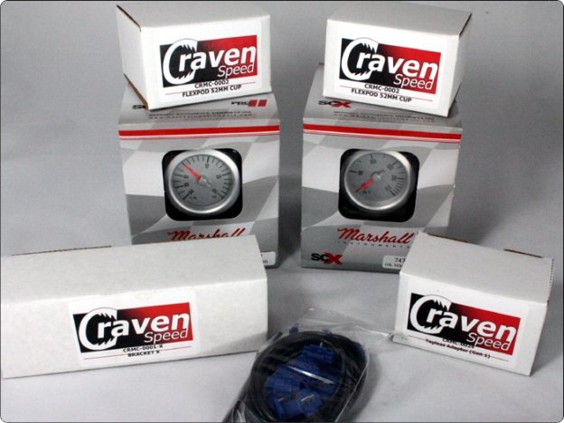
Parts Included:
- 2 Gauges requested (Boost/Vac / Coolant Temp / Oil Pressure / Oil Temp / Volts)
- All necessary wiring and senders
- All necessary sender adapters and hardware
- Gauge Pod Mounting Bracket and hardware
- 2 Gauge Pods and hardware
- Brass Tubing
- Zipties
Tools Required:
- Ratchet Wrench with Metric Sockets
- Masking Tape
- Philips and Standard Head Screwdrivers
- Transfer Pump or Siphon
- Clean Rag or Plastic Bag
- T20, T25 and T30 Torx Drivers
- 3/16" Hex Wrench
- Adjustable Wrench
- Trim Panel Removal Tool (standard screwdriver will work with caution)
- Cordless Drill with 3/16" and ¼" Drill Bits
- Rotary Tool with Cut-off Disc Attachment (Dremel)
- 12v Test Light
- Wire Strippers
- Wire Connector Crimper Tool
- Hose Cutter (coolant gauge install only)
This kit is suitable for for R56, R58, R59, and R60 with Refresh Engines (2011+) .
Please read instructions completely before installing. These instructions contain the information required to install a variety of gauges, so some of the information may not pertain to your build.
• ALWAYS WEAR SAFETY GLASSES.
• Install gauges only when engine is cool and ignition is off.
• Make sure all necessary tools, materials, and parts are on hand.
• Disconnect negative (-) battery cable before installing gauge.
• Make sure mounting location does not impair visibility or interfere with driving.
• If you must drill, always check behind the mounting location for any wiring or components before doing so.
Procedure
Preparation for Installation of Sender(s)
- Determine routing for PVC tubing for Boost and/or wiring for Oil Pressure, Water Pressure, Oil Temp or Water Temp gauge(s)
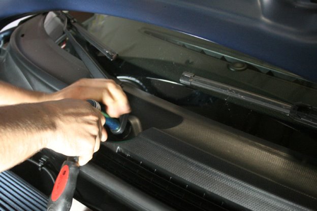
- Remove both windshield wipers. Be sure to mark the wiper location on the windshield with masking tape. Flip up the hinge covers and remove the nut on each wiper. The wipers are taper-fit and need to be pulled off. They should be fairly tight, so it may take some pulling/rocking to get them to come loose. Be careful to keep the wiper spring from jumping from the wiper assembly. If the spring disconnects, you may have some difficulty reattaching it.
- After the wipers have been removed you will be able to remove the two 10mm nuts holding the cowl cover in place and have access to the hole in the firewall. We find that it is fairly easy to feed the new wires through the same firewall hole that the hood latch uses.
Prep for Boost, Water Temp and Oil PSI Gauge Adapter Installation
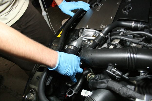
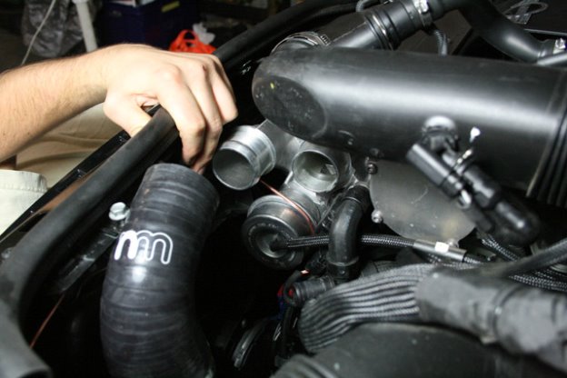
- Use a flathead screwdriver to loosen the hose clamps on the hose connecting the air box to the intake on the turbo. Pull the hose back from the air box.
- Loosen the hose clamp around the intake hose connected to the air filter box.
- Unplug the MAF sensor and place the intake tube to the side.
- Loosen the hose clamp around the intake hose connecting the turbo to the intercooler.
- Now loosen the hose clamp that is down the hose near the intercooler. Remove the hose and set aside.
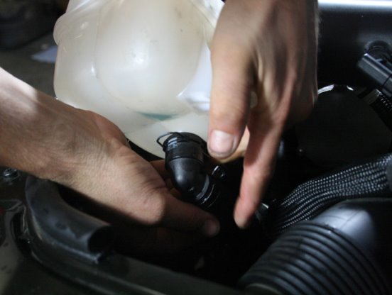
- Drain the coolant expansion tank using a transfer pump or by siphoning. Alternatively, the coolant can be drained into a pan placed below the car by disconnecting the hose on the bottom of the tank (this method can be a bit messy).
- Once the coolant expansion tank and tubes connected to it are empty, go ahead and remove the tank itself by removing the 2 bolts and disconnecting all tubing.
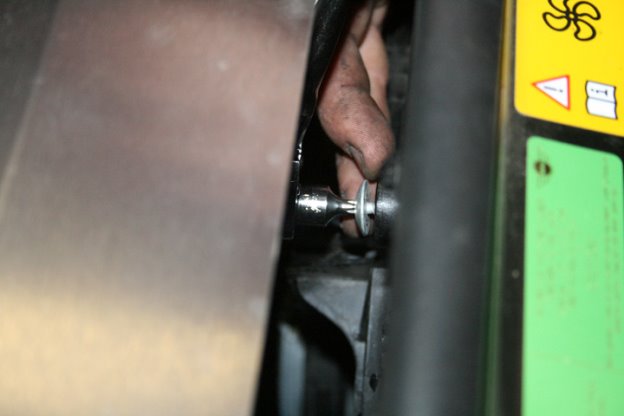
- Detach the engine cooling fan for the oil pressure gauge installation. Do this by first disconnecting the wiring harness attached to the fan. Next, remove the 2 retainer bolts. One is located on the top of the fan and the second is located on the bottom. You may have to access the bottom bolt from underneath the car. Move the fan to the side.
Install the Tapless Oil Pressure Adapter
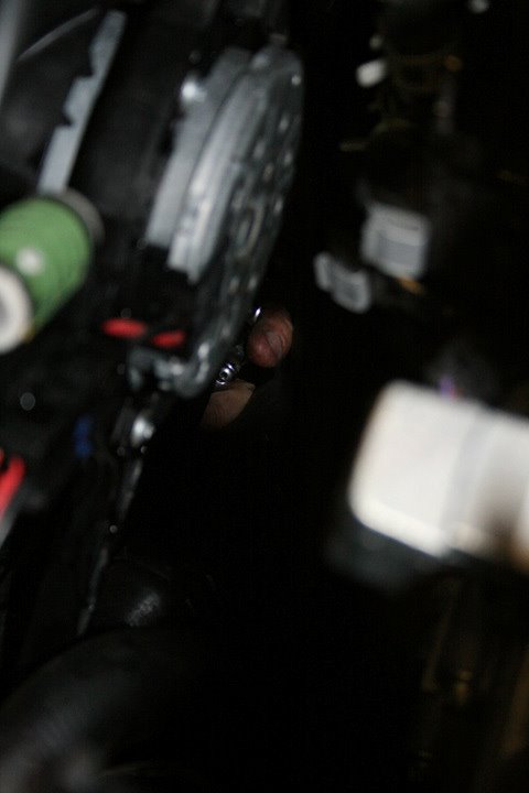
- Locate the factory Oil Pressure Sensor – it is behind the plastic oil filter cover on the oil filter housing. It is brass with a black plastic connector on the end.
- Remove the wiring connector by pushing on the plastic lock tab and gently pulling/rocking it off the factory oil pressure sensor.
- Remove the factory sensor by using a 24mm deep well socket and ratchet wrench.
- It's a good idea to keep this sensor clean after removal by wrapping it in a rag or placing it into a clean plastic bag.
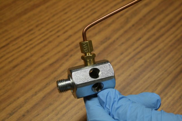
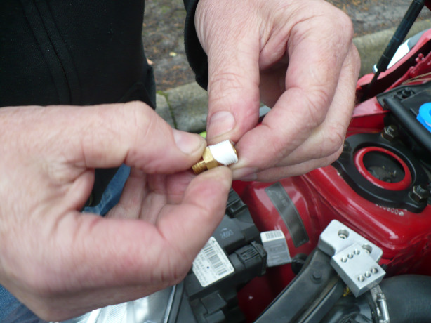
- Tightly insert one of the included 1/8" npt plugs into the tapless adapter part #1. Next put the rubber gasket ring onto the male end of the adapter and tightly insert it into the factory Oil Pressure Sensor cavity.
- Insert the factory oil pressure sensor into the end of the adapter.
- Choose the most accessible port on the adapter and remove this plug.
- Connect the straight ⅛" npt compression fitting to the open port on the adapter. It is recommended to use Teflon tape or some other oil-resistant thread sealant.
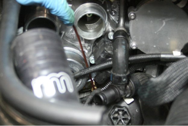
- Attach the included brass tubing to the compression fitting and then add the female 1/8" npt compression fitting to the end of this tubing. It may be necessary to bend the remote tube at up to a 45 degree angle before attaching in order to avoid obstruction of the oil filter cover. (Make sure to install the remote tube after the tapless adapter has been installed, unlike the illustration below) Be very careful bending the remote tube.. always do it slowly and do not overbend or crimp the tube.
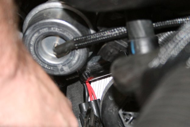
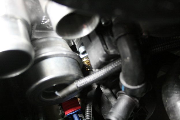
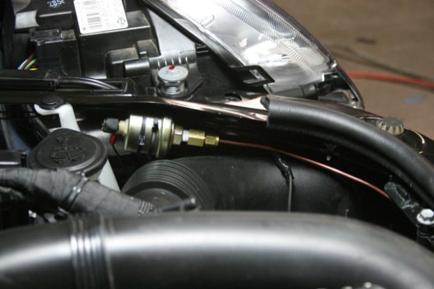
- Route the copper remote tube up between the turbo inlets and toward the front of the car. Take care to avoid the hood latch mechanism.
- Attach the sending unit from the included gauge to the female end of the compression fitting and secure the sender to the lock bridge using the included zip ties.
- Reconnect the factory Oil Pressure Sensor wiring harness.
- Attach the gauge sensor wire to the sending unit. Run the sensor wire through the existing break-line slot in the cowl, and then through the hole in the firewall. Again, we find that it is fairly easy to share the firewall hole that the hood latch cable uses.
- Make sure to secure the wiring to prevent damage from sharp edges, moving parts, or hot engine components.
- Reinstall engine cooling fan, air intake hoses and coolant expansion tank.
- To finish with the Marshall gauge installation and wiring click here for instructions.
Install the PSIclone Boost Adapter
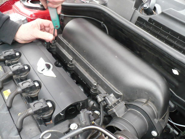
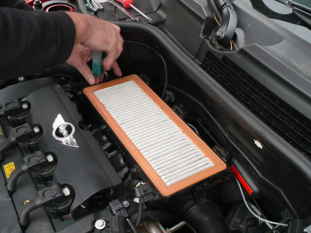
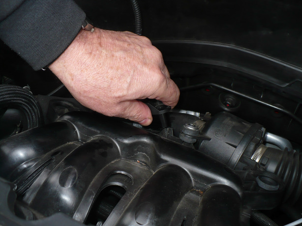
- Using a T-25 Torx driver, loosen the 4 screws around the air filter housing lid and take it off.
- On the left side of the air filter, unscrew one screw using a T-25 Torx driver.
- Pop the air box off the mounting points and roll the base up and to the cars left, leaving it connected to the lower hose.
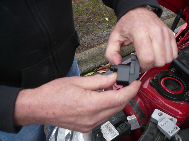
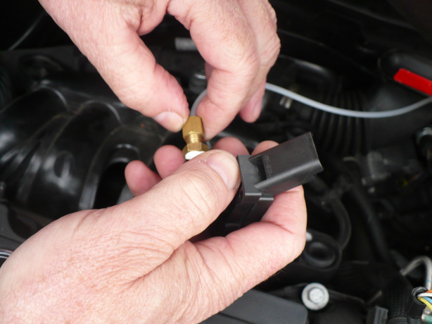
- Disconnect the plug from the OEM sending unit.
- Remove the sending unit.. it just pulls out after the bolt is removed.
- Place the included o-ring onto the PSIclone adapter if it has not already been done.
- Fit the PSIclone adapter together with the OEM sending unit.
- Place 2 wraps of Teflon tape or suitable thread sealant on the included brass connector threads.
- Install the connector into the 1/8" npt tapped hole on the PSIclone adapter with an adjustable wrench.
- Connect the gauge unit PVC tubing to the brass connector.
- Press the PSIclone with the o-ring into the hole where the sending unit was, making sure to line up the holes for the T-25 Torx screw.
- Put the T-25 Torx screw through the holes on the sending unit and the PSIclone.
- Tighten the screw with T25 Torx Driver.
- Plug the OEM sending unit wire harness plug back into place.
- Run the PVC tubing through the existing break-line slot in the cowl, and then through the hole in the firewall. Make sure to secure the tubing to prevent damage from sharp edges, moving parts or hot engine components.
- Cut off one of the tips of an existing nipple in the rubber covering and run the tube through this cover and then up the steering column.
NOTE. Marshall Gauges has discontinued its MECHANICAL boost gauge, and now only offers stepper gauges. The most important difference here is that the sending unit should NOT be installed directly onto the adapter. You will need to mount your sending unit as far from the heat of the engine as possible. Please contact us if you have any questions.
Attaching the HotLink Water Temp Adapter
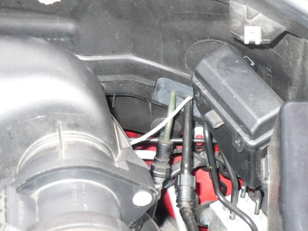
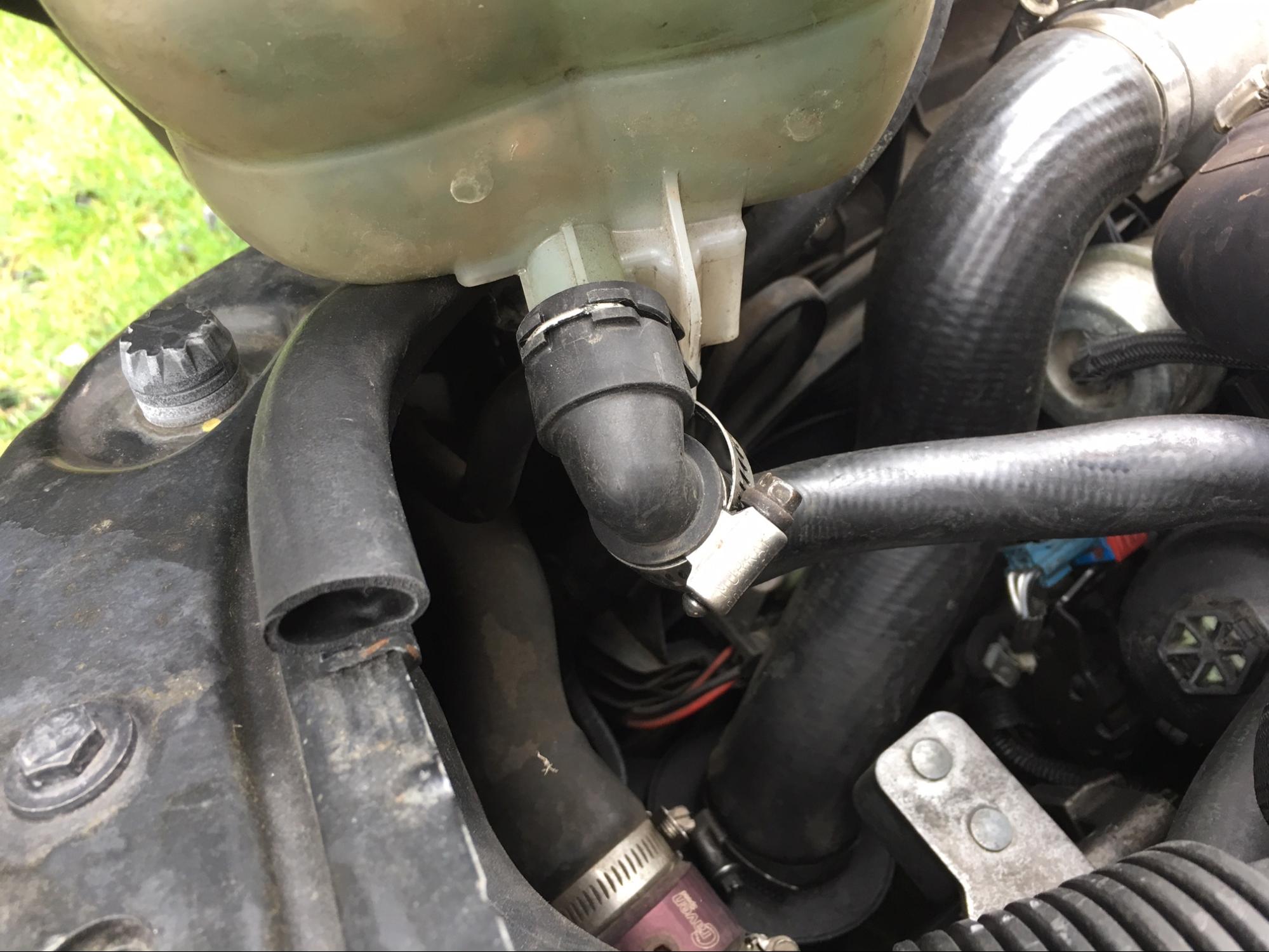
- Utilizing your 8mm socket wrench, remove the coolant overflow tank on the front driver side of the engine compartment. You can either choose to work around it, or drain the coolant from it and temporarily remove it from your MINI. Once empty, pry the wire clip out a bit and disconnect the plastic elbow from the underside.
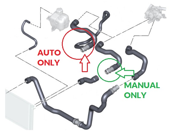
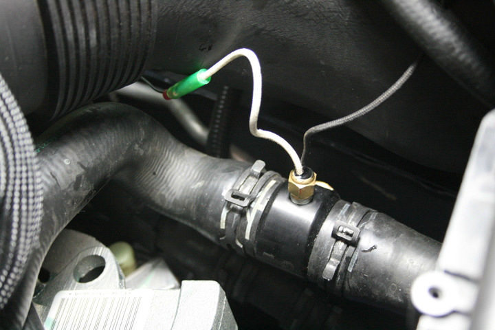
- Now that you have access to the area underneath the coolant overflow, locate the coolant hose alongside the outer engine compartment wall and you should see a plastic inline coupler. The CravenSpeed Hot Link simply replaces this coupler. In the manual transmission MINIs this coupler is straight, but in automatics this coupler has a smaller t-fitting in the center that goes to the transmission. See image below.
- Prepare the Hot Link by applying some thread sealant/Teflon tape to the threads of your gauge temp sender (included with your gauge kit) and install it into the smaller of the two threaded holes. For manual transmission MINIs, install the ⅜” brass plug with a 5/16” hex driver into the remaining threaded hole utilizing your preferred thread sealant. For automatic transmission MINIs, install the ⅝” brass barbed hose fitting using your thread sealant.
- For this next step, be prepared to spill a bit of coolant so place a drain pan on the floor directly underneath your work area. Use coolant hose pinch pliers if you have them, otherwise recruit a friend to help stem the flow of coolant while you remove the factory hose coupler. You can loosen the factory hose clamps with an adjustable wrench by pinching the metal ends together. Remove the two main factory hose clamps as we’ve provided higher quality units in this kit. For automatics, reuse the hose clamp from that fitting if there is one. /li>
- With the factory hose coupler removed, slip the included hose clamps loosely over the coolant hoses and then install the CravenSpeed Hot Link, pushing the hoses all the way up against the center section of the Hot Link housing. Slip the hose clamps into position and tighten.
- Perform the necessary wiring as outlined in your gauge instructions. Replace your coolant overflow tank hose and reattach it to the front core support.
- If you’ve lost very much coolant over the course of this install, top it back off with what’s recommended by the factory.
Please be sure to clean up any spilled coolant that may be left on the ground as it is extremely attractive and harmful to our furry friends.
Attaching the Oil Temp Adapter
- Raise the car. Jack Stands should always be used.
- Loosen the oil filler cap.
- Assemble the oil temp sensor and the drain plug adapter so you have a new, leak free oil drain plug.
- Do not let the oil drain yet, but start unscrewing the oil drain plug. If you are going to do an oil change, now is the time; if not, wear gloves and you may be able to plug the leak and swap the plugs with limited oil loss. Be prepared for the oil spillage either way.
- When you install the oil drain plug adapter, use the included o-ring or factory crush washer from the OEM plug. We recommend a new crush washer when possible. Torque spec on the drain plug is 22.0 lbs/ft.
- When routing the wire from the new sensor to the gauge, take care to notice all moving parts and remember that some of this wire is exposed beneath the vehicle. Take precaution to prevent the wire from being severed by road hazards.
Attaching the Bracket A
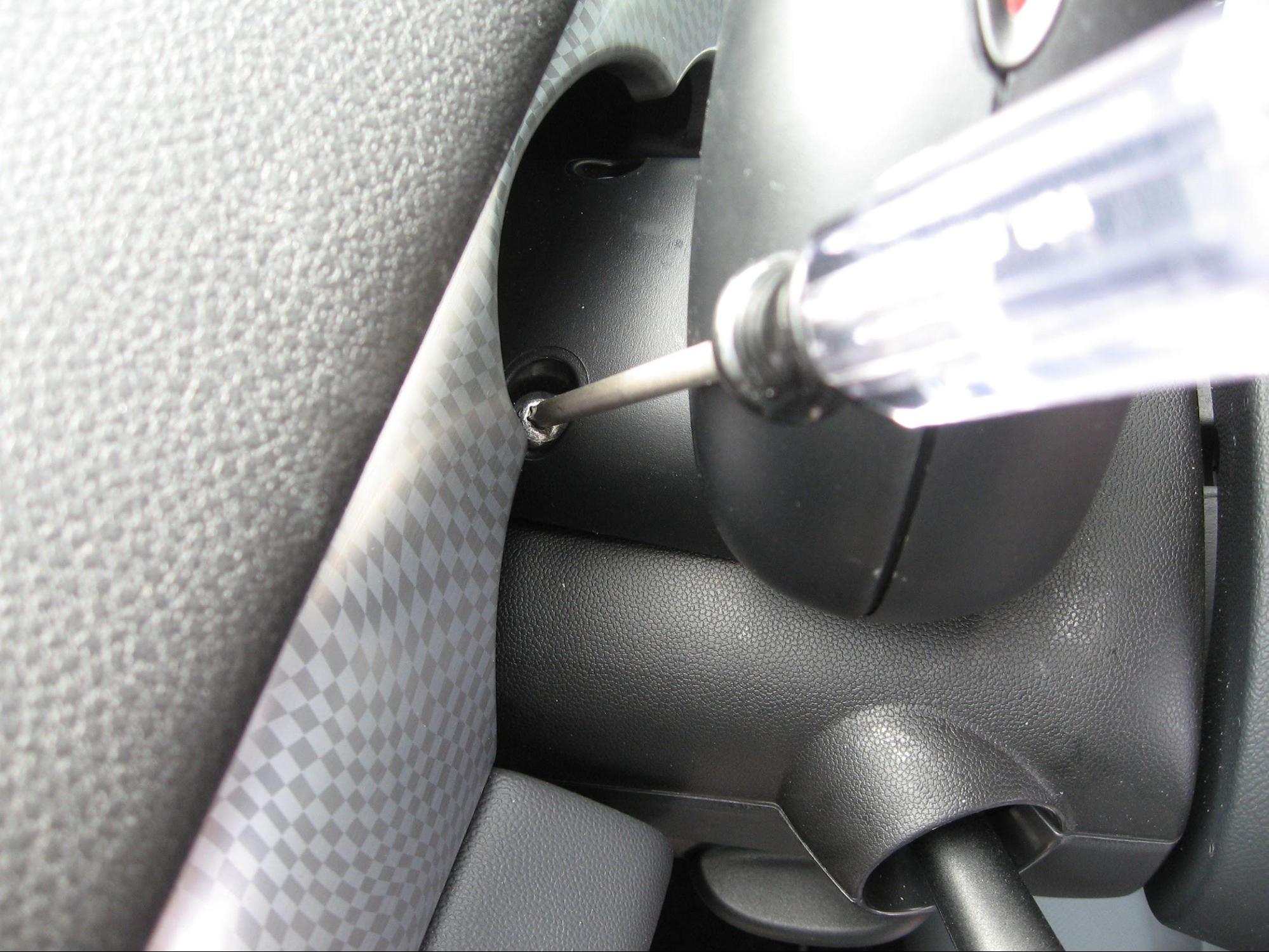
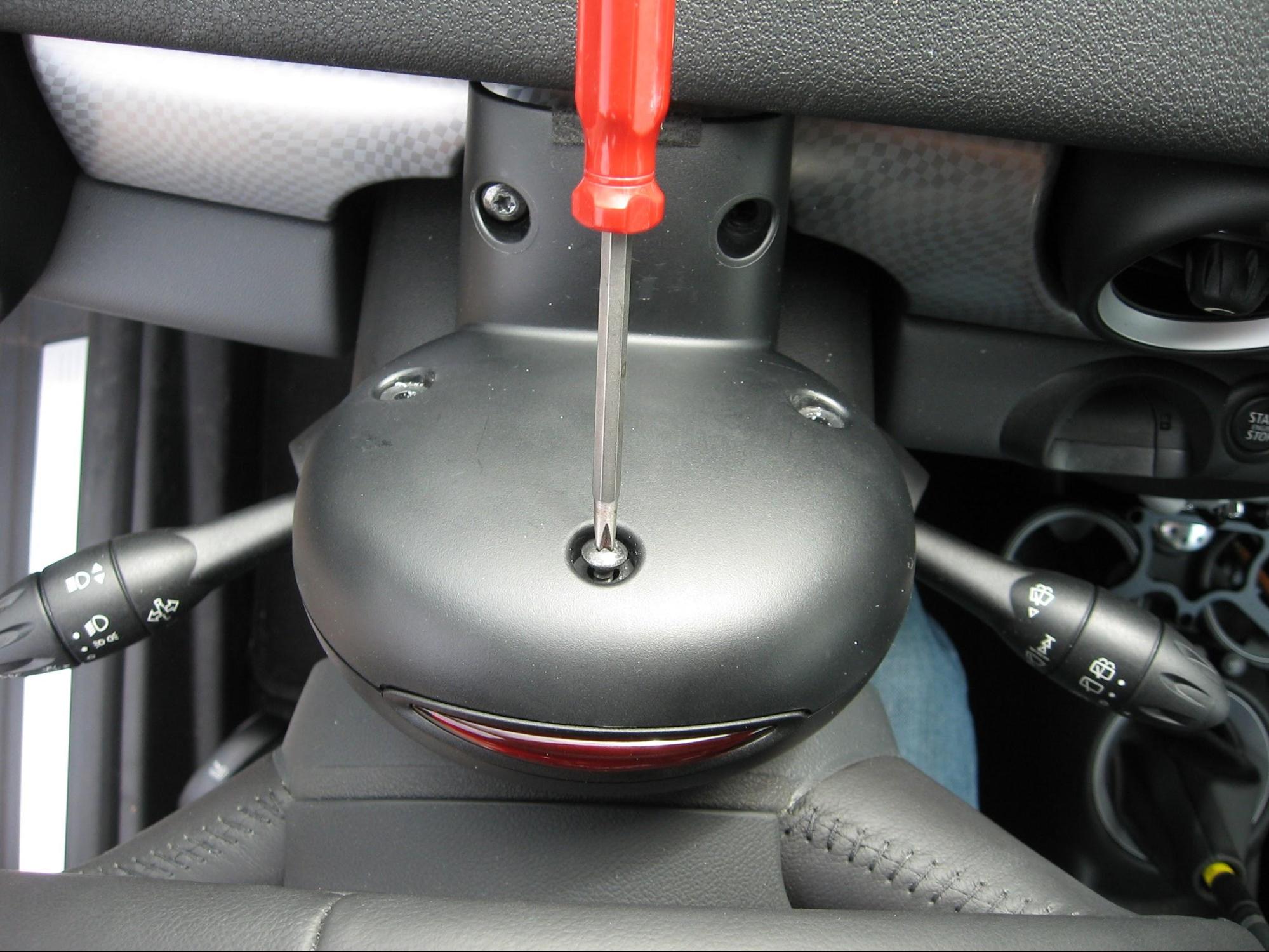
- Remove factory mounting screws behind tachometer using a T27 Torx driver.
- Keep these Torx screws safe as you will need them again during re-installation.
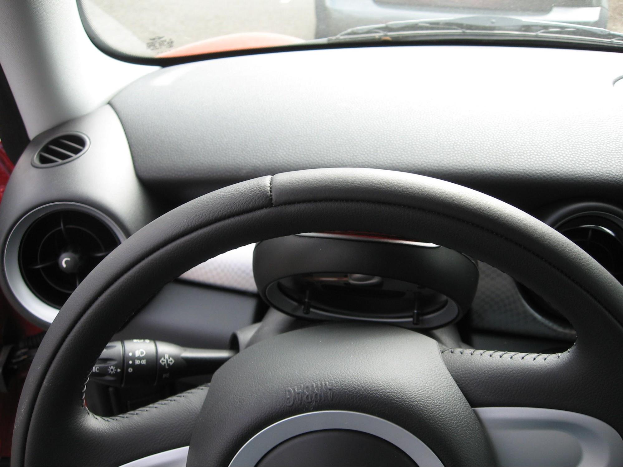
- Pull the tach towards you and slide it off the hidden mounting rail.
- Lean the tach towards the wheel to gain access to the 3 screws on the back of it.
- Using a Phillips screwdriver, remove the three screws on the back cover of the tach.
- You may wish to keep the OEM screws, but you will not need them for this install.
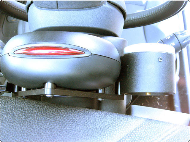
- Place the plastic spacers into their corresponding holes then set the Bracket A into place.
- Affix the Bracket A with the included Plastite screws.
- Make sure the bracket is snug and does not wobble, but do not over-tighten and risk stripping the plastic housing threads.
- Place the tach back in its original position and re-attach it with the T-27 Torx screws.
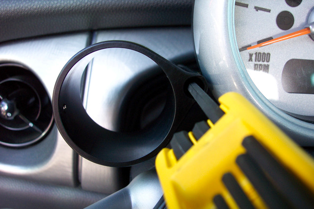
Add a 52mm Gauge Cup to each mounting point on the Bracket A
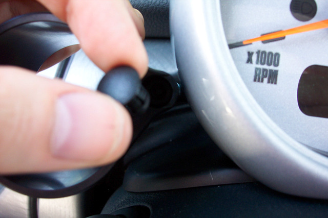
- Attach a gauge cup to the mounting hole in the bracket using a ¼"-20 hex cap screw and plastic spacer then adjust to desired height.
- Use included plastic plugs to cover the gauge cup mounting screws.
- Insert the gauge allowing its studs to go through the holes in the half-moon back plate. Tighten the thumb nuts included with your gauge to the studs.
- Alternately, for gauges that do not have mounting studs, you may utilize the included round foam pads to create a resistance fit; stick the foam pads to the inside of the gauge cup and slowly but firmly insert your gauge. Start with one foam pad and if it is not tight enough, add a second one and so on.
- Plug all required wiring into the gauges and insert them into each cup.
- Cut excess PVC tubing and plug it into the boost gauge.
Gauge Installation and Wiring
NOTE: We do not carry the dimmer controller in our kits, however they can be purchased directly from Marshall Instruments.
- In case it has not already been done, please disconnect negative (-) battery cable before continuing. This step will make it easier to keep from accidental blown fuses or zappy-zap moments.
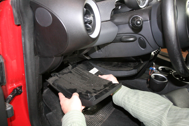
- Remove the kick panel below the steering column and the heater core cover next to the driver’s leg to determine the path of the wiring.
- Remove the center console to gain access to the 12v. plug wiring harness. This is performed by removing the 3 screws, one in each cup holder.
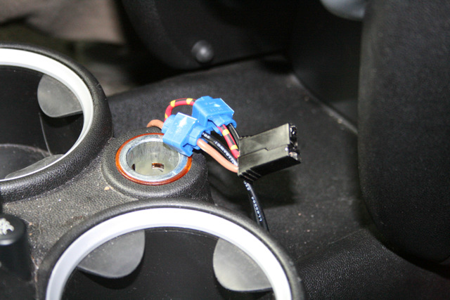
- Plug in the wiring harnesses that came with each gauge (if applicable) and place the gauges into each of the gauge cups you installed prior (see photo below).
- Using the included 22 AWG solid wire, connect the BLACK wire from the gauge to the BROWN ground wire on the cigarette lighter wiring harness.
- Connect RED wire from the gauge to a 12v (+) ignition source. This is the RED with YELLOW stripe wire, also located on the cigarette lighter wiring harness.
- (OPTIONAL) For white back light, connect the WHITE wire to dash lighting circuit instead of the ORANGE wire.
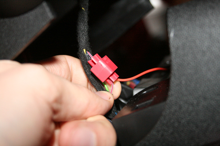
- For Stepper Gauges only, connect the PURPLE wire from the gauge to a constant 12v (+) source. You’ll find this going into the OBD II port under the kick panel. The wire will be RED with a BLUE stripe. Easy access to the wire can be obtained by removing the 2 retaining screws on the OBD plug.
- Run all wiring behind the panels that were removed earlier and up through and behind the steering column.
NOTE: You will need to keep tach lighting at full brightness for the LEDs in the Marshall gauges to function. For amber back light that matches your factory MINI gauges, connect the ORANGE wire to the dash lighting circuit. You’ll find a lighting wire underneath the center console directly beneath the lighter socket. It will be the GRAY wire w/ RED STRIPE.
Put it all back together
- Work backwards in reverse order – putting back the air filter, the MAF sensor, and the turbo inlet hose.
- Reconnect the intake hose, securing with hose clamps. Verify there are no leaks.
- Re-attach all cover panels. Re-install windshield wipers using the tape markings you made earlier.
- Reconnect negative (-) battery cable. Start and run engine for approximately 30 seconds then turn it off and check gauge installation for leaks. Tighten or reseal tubing connections as needed, wait until the engine has cooled and retest.
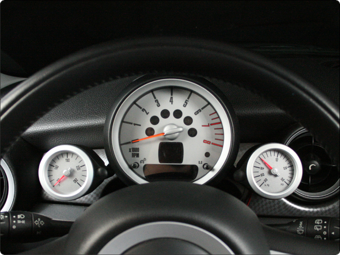
Enjoy your new Gauges!
Boost/Vacuum - The boost gauge shows both vacuum and boost and although your turbo-charged MINI will read vacuum much of the time, you will only register boost under hard acceleration. Reading will vary, but full boost on a stock MINI should be about 11.5 psi.
Oil Temp - The oil temperature level should hover around 200 degrees under normal conditions. Oil temps can reach over 230, but at this point the viscosity of the lubricant is breaking down and can begin to cause damage to the engine.
Water Temp - Normal water readings are in the 220-230 degrees. Higher temps lead to increased pressure in the system and indicate that there could be other problems.
Voltage - Normal voltage when the car is off would be around 12.5v. If the alternator is running and functioning normally then you should be reading approx 14v.
Oil Pressure - Oil Pressure is not static. At idle the pressure should be around 30 psi. As the RPMs increase, so will pressure. There is no need for concern until around 90 psi.
Air/Fuel Ratio - Your MINI should be running approx 14.7 AFR at idle or at light load. When you start getting on the pedal, it will start getting richer eventually reaching 11.0 or so at full load.
Troubleshooting
-
Problem: Gauges are not lighting up
Possible solution: Re-check all wiring to make sure that the correct connections have been made. -
Problem: Gauge needle flutters
Possible solution: check to make sure that all the electrical connections are secure and that a strong ground connection has been made. -
Problem: Lights are showing white (red) when they should be red (white)
Possible solution: Make sure that the red (white) wire is connected to the GRAY wire under the center console. -
Problem: Boost gauge shows lower than expected boost.
Possible solution: Check for any leaks in the boost line.
If you have any questions about this installation, please give us a call at (503) 505-6886 from Monday - Friday between 8am and 4:30pm Pacific Time and we will be glad to give you a hand.