THANK YOU for purchasing the Fiat 500 Water Methanol Injection Kit from CravenSpeed. This product is made from the highest grade materials, and is guaranteed to be free from defects.
Parts Included:
- 1 Recirculation Pump
- 4 Pump mounting bolts with associated nuts and washers
- Grounding point bolt with nut and lock washer
- Check Valve
- Pressure Switch (Boost Activated) with fitting
- 1 Tank Tap
- (1) Two GPH nozzle
- 1 Nozzle Holder
- 15ft Nylon Hose
- Boost Line 6 of 8mm with 2 feet of 4mm JOINED together
- 1 Green LED - System ON Light
- 15 each male and female insulated connectors (30 total)
- 5 ft Wire Loom
- 1 Relay Socket/Harness
- 10 ft Red and Black 16GA wire
- 4 One Ring Connectors
- 3 Blue Posi-TapTM
- 1 Fuse Holder
- 5-6 Long Zip Ties
Tools Required:
- Drill with 11/32 bits (smaller bits for pilot holes will be helpful with drilling)
- 1/8 NPT Tap (you can get one from the local hardware store)
- 7/8 Drill Bit for Tapping Reservoir
- 18mm wrench
- 7/16 wrench
- 9/16 wrench
- 1/4 socket with ratchet
- Wire cutters
- Electrical tape (Recommended)
- Small metric socket set - preferably 1⁄4 drive with Torx fittings and a normal selection of small metric sockets. A selection of extensions and a universal joint will really help
Safety:
Always wear protective eye cover when working with pressurized hoses, especially those containing methanol. Disconnect the negative side of the battery whenever doing any electrical work, or when working underneath a car. Never carry flammable liquid in a car outside of approved containers.
This system will not solve a problem your car already has. If your car is overheating, running lean, or has some other issue, fix it before installing this system to avoid confusion when troubleshooting.
Teflon Sealing tape should NOT be used on any fittings in this kit. Liquid thread sealer is fine in small amounts. Be careful not to plug or clog the tiny orifices in the nozzle or nozzle’s filter.
If your pump was accidentally switched on for any reason while the engine was not running DO NOT attempt to start the engine or crank it over. If you do, serious damage could result. You will have to remove the spark plugs and crank it over by hand, or carefully push it while in gear to ensure there is no water in the cylinders. Then install the spark plugs and start the engine.
DO NOT modify the injection pump in any way.
DO NOT PUMP FLAMMABLE LIQUIDS. DO NOT PUMP MORE THAN 50/50 MIX OF ALCOHOL (METHANOL) AND WATER! MORE THAN 50% ALCOHOL (METHANOL) IS A FLAMMABLE LIQUID
Procedure
It’s time to start installing your kit. Start at the back and work forwards. It gives the illusion of more rapid progress that way, making the project seem to go faster!
Tank and Pump Installation, Windshield Washer Reservoir (if you purchased the Street Kit)
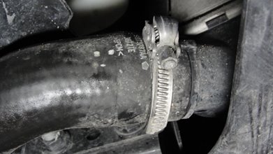
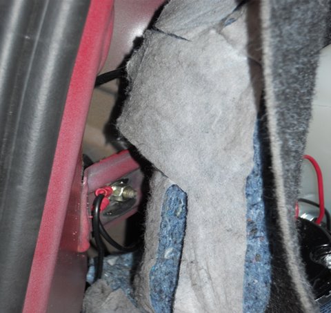
Begin by removing the plastic wheel well cover screws and fender area. This will make it easier to access the windshield washer tank located on the passenger side of the engine bay. You will be working from underneath the car. Also, you may want to remove the intercooler piping piece and clamp pictured below to make fitting a drill easier.
Remove this piece of intercooler piping:
Next, drill and tap the tank. Start with a smaller pilot hole, and then use your 7/8 drill bit to finish. Our picture below shows the recommended spot.

Now, take your included tank tap and insert into your hole in the windshield washer reservoir, and tighten to seal. A piece of nylon tubing will run from this tap to your pump.
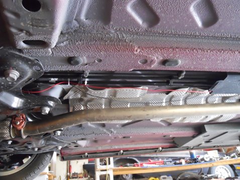
You will be bolting and installing your pump onto the passenger side of the undercar belly pan, right above the ducting ventilation. Start by removing your belly pan, and position the pump to test fit before marking and drilling your holes.
See pictures below:
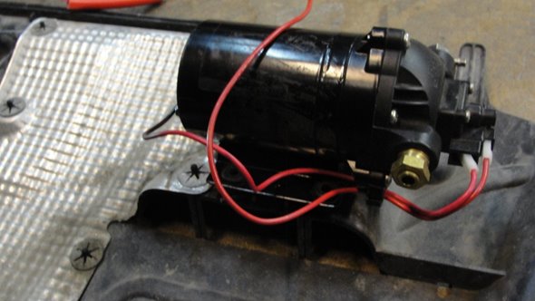
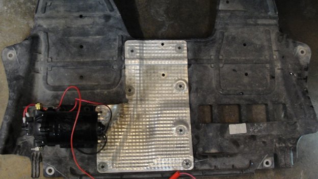
Drill your holes, and use the included pump mounting hardware to secure the pump to the bellypan. Leave the bellypan off for now, as you will need to finish your hose routing from the pump before it’s re-installed.
The rest of the instructions below detail plumbing to the nozzles and wiring. You will need to locate a new grounding spot for the pump in the engine bay. You will not have to route the plumbing from the trunk to the engine bay, so you will use less hose and wiring. However, be sure to leave enough slack so you can remove the bellypan without pulling any wiring or nylon hose. Note: You will not be installing the RED LOW LEVEL LIGHT later in the instructions. The cars low level sensor in the washer reservoir will indicate when your fluid level is low.
Tank and Pump Installation, Standard 1 Gallon Tank (if you have the 2.25 gallon tank, see later page):
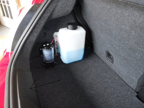
Begin by removing the plastic panel at the rear of the trunk. It’s held in with screws and once they are removed it simply pops out. Take care when pulling it free so you don’t break anything. Next remove the trunk carpet. This is sometimes a little bit of a struggle as it’s attached to a stiff board and is shoved under the amplifier mounted on the passenger’s side of the trunk.
Next, we need to gain access behind the panel covering on the driver’s side of the trunk where we will be mounting the tank and pump. You do NOT need to remove this panel. Just remove the screws, pull back the weather-stripping a little bit and the panel will come far enough away from the side of the car to get your hand in there and work.The arrow in the picture below points to the plastic panel that must be removed first. Next remove the trunk carpet, unscrew and pull back the panel on the driver’s side of the trunk. The tank and pump in this picture are actually mounted a little too low. An inch or so higher would have been better for easy access. You can see the tank tap near the bottom of the tank on the rearward facing side. The low level switch is just out of view on the other side.
Next, it’s time to mount the tank and pump. It’s as easy as it looks. Mark the location of the holes you need to drill in the side panel and drill them. Be careful not to go too far through the panel as we don’t want to scratch anything on the other side (it’s the inner fender so if you do it won’t be visible anyway).
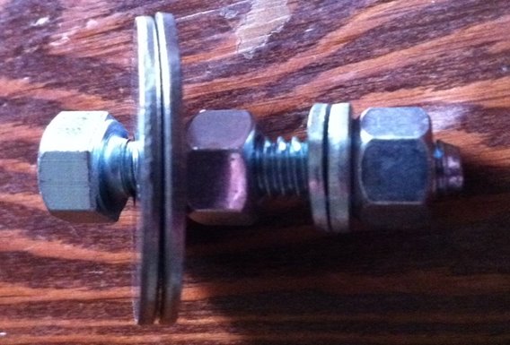
Now, it’s time to bold up the tank. Each of the four bolts has two nuts, two big washers, and two small washers. The two big washers go on either side of the panel. The two small washers go on either side of the tank. The bolt goes through the first big washer, then the panel, then the other big washer and is secured with the first nut. Then a small washer goes on, the bolt goes through the tank, then the other washer and the last nut secures it. (see picture below)
Pictured below is the order of the tank mounting hardware. The side panel in the trunk should be sandwiched between the two big washers and the tank’s mounting tabs between the two small washers.
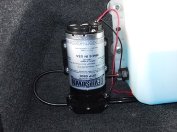
Once the tank is mounted, it’s time to mount the pump. Before mounting the pump, take note of the arrows near the inlet and outlet so you can keep track of which is which. The mounting procedure is very similar using 4 bolts and a combination of associated parts. Again, the trunk panel is sandwiched between two large washers. Then the pump is shoved onto the bolts. The remaining big washer, lock washer and nut secure the pump.
Now that the tank and pump are mounted, we are going to do the plumbing at the rear of the car. First, let’s attach the hose going from the tank’s outlet to the pump’s inlet. The hose just shoves into the fittings. To release it you push in on the fitting, hold it in and pull out the hose.
Connect the tank’s outlet to the pump’s inlet as shown in the picture below.
Trunk Plumbing, CHECK VALVE and Wiring:
Now it’s time to plumb the pump’s outlet. Fiat provided us a nice path to take the hose, so we don’t need to drill any holes. Take the hose from the pump’s outlet and route it to the check valve. Look at the arrows on the check valve and make sure it’s going the right way. Then insert another hose going out of the check valve and without kinking it, snake it out of the trunk through the cabin exhaust outlet at the rear. I suggest protecting the hose with a slit piece of the included tubing as shown in the picture below.
The pump’s output line exits the trunk through the cabin exhaust vent at the rear. Do this before you put the trunk carpet back in.
For now leave the hose under the car, we will come back to routing it up front once we finish in the trunk.
Both the pump’s ground wire (that’s the black wire on the pump) and the low level switch’s ground wire (either wire on the switch will work) will need to be connected. Again, Fiat provided us with an excellent factory ground location. No need to drill any holes. First, locate the grounding location behind the driver’s side panel where the tank and pump are mounted to. Next, take some black wire, use the included connectors and extend them so they are long enough to go under the side panel and up to the grounding point.
Find the included grounding point bolt, nut and lock washer and matching ring connectors. Put the ring connectors on the wires and bolt them to the grounding point.
The top of the pump can be seen in the upper right hand corner of the photo. The two wires are shown bolted to the grounding point. It’s behind the panel near the weather-stripping.
Now we have the other two wires in the trunk to deal with. One is the pump’s red power wire. This one is critical. If this wire shorts to ground anywhere, an electrical fire could result. In theory, the fuse would protect against that, but let’s not find out. So we need to be careful not to let it rub up against anything that could wear through its insulation and make sure all connection points are insulated and can’t touch anything metal. The other wire we will be working with right now is the second wire on the low level switch. If it shorts to ground, nothing will be damaged, but it will cause the low level light to illuminate regardless of float position.
Both of these wires need to be extended. The red power wire will need to be long enough to reach the front bumper. It’s not going there, but that’s about how long it needs to be. The low level switch wire needs to be long enough to reach the front wheels.
Remove the bottom seat cushion portion of the back seat. On the vertical surface under the seat on the driver’s side is a rubber grommet. Route the wires under the rear seat, poke a hole in the grommet and pass the wires through them.
Now you can put everything in the trunk back together, carpet, plastic panel, all screws, everything. Reinstall the rear seat. We are done with the back end of the car.
Routing the Hose and Wiring to the Front of the Car:
It’s time for some good news. Once again, Fiat provided us with a good solution for our routing pathway. The factory provided plastic ducting to protect various factory lines and left enough room for our hose and two electrical wires.
Start by taking the hose that exited the trunk at the cabin exhaust outlet and route it over the fuel tank. Then route it over to the area where the two wires exit the cabin. Take your time here and make sure it doesn’t kink and can’t be pinched by any moving suspension parts, burned by exhaust of have any other problems. The idea is to get the hose near where the two wires exiting the cabin as all three will need to travel to the front of the car together.
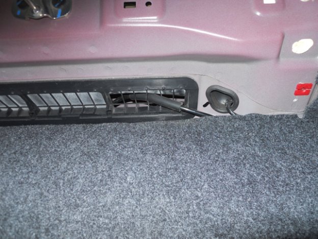
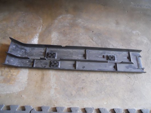
Underneath the car on the driver’s side is a two piece plastic duct that’s held on with a number of small bolts. It’s easy to unbolt and remove these pieces. The front piece comes out very easily, the rear piece has to be wrestled out once unbolted but it comes out.
The picture below shows the forward section of the plastic duct removed, the rear section is in view on the right side of the picture.
Notice the plastic ducting has locating ridges. It’s important that the hose and wires go straight so they don’t cross over and risk getting pinched by these ridges when you put the ducting back on and tighten the bolts.
Once the hose and wires are routed up to the front, reinstall the plastic duct pieces.Remove the forward splash shield that covers up the bottom of the engine bay. Route the hose and wires forward being careful to avoid anything that moves, steering, axles, suspension parts, etc. I suggest going over the forward anti-sway bar and up on the driver’s side of the car.
Now is an excellent stopping point. If you need to continue this another day, you can coil up the wires and hose and secure them somewhere safe in the engine bay. Put tape over the hose outlet to keep contaminates out.
Let’s tuck the wiring away somewhere safe and finish the plumbing first. That way the system will be sealed and keeping dirt and debris out.
Nozzle Installation and Final Plumbing Work:
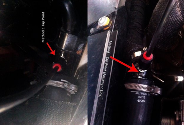
Your kit includes dual nozzles. They should be installed after the intercoolers.
Method: Drill and Tap.
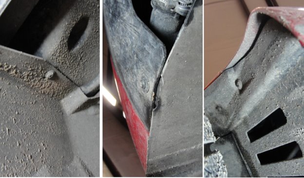
After each intercooler there is a rubber coupler that connects to a hard metal pipe. These hard metal pipes join up and form one larger pipe heading to the engine. You can drill and tap the metal pipe and simply thread the nozzle directly into it. All this work can be done with the metal pipe on the car, so there is no need to remove it.
You must drill the hole near the end of the pipe an inch or two from where it attaches to the coupler. You MUST be able to feel inside the pipe with your finger in the area where you drill the hole. For that reason you can’t drill the hole too far away from the coupler.
To do this, first remove the coupler. Shove a wet rag into the pipe past where you will drill the hole. This will help prevent metal shavings from entering the engine! Now mark where you want to drill.
Once the nozzle location is marked you will need to drill the hole. The hole needs to be 11/32. Caution: a 3/8 drill bit looks almost exactly the same but it needs to be 11/32. I suggest drilling a small pilot hole first as it will help the 11/32 bit make a really nice hole. It’s time to use your 1/8 NPT tap to tap the hole and make nice threads for our nozzle. Be careful not to go too deep with the tap or it can actually dig into the pipe on the other side. Also, as the tap goes deeper and deeper as the hole gets wider. You only want it to be wide enough so the nozzle can thread in.
It’s time to make sure you get ALL the metal filings out of the pipe. You can run a magnet through there over and over until you don’t see any more metal filings. Use your fingers to feel for any metal shavings or burrs where you drilled and tapped that could break off. If there are any, carefully remove them with a tiny file, being careful not to damage the threads you just tapped. Once it seems perfectly clean, pull out the rag and repeat the process with the magnet and your fingers until you are sure there is no metal in there.
Repeat this process on the other side for the 2nd nozzle.
Now locate your nozzle, make sure the filter screen is snug. Don’t twist it too hard or it can deform and decrease flow rate to the nozzle. Use a tiny bit of liquid thread sealant and screw the nozzle by hand into the hole you tapped. The side with the nozzle hole goes down into hole, the filter is the inlet side that fits into the nozzle holder. Get it as tight as you can with your fingers. Now screw the nozzle holder onto the nozzle. Don’t over tighten, snug is good enough, the threads here are delicate. The NPT threads do the sealing for us.
Connect the nylon tubing from each nozzle to the pump tubing via a provided metal T or splitter. These have instant connect fittings as well for your tubing. Firmly slide in the tubing to the fittings on the splitter. You will need to route it up to the front of the car and make sure it can’t get caught in the steering or suspension. Make sure it’s not touching the exhaust. Plug it into the nozzle holder and your plumbing work it done.
Pressure Switch:
This part of the installation is fairly easy. The system operates as follows. A pressure switch senses boost. When boost rises above the desired level (we recommend 10-12psi in the Abarth) the switch closes and connects the relay to ground. The relay then closes and connects battery power to the pump causing it to run. Don’t worry. We will go over it wire, by wire.
The pressure switch mounts to the firewall with the included zip-tie. Be sure to secure the pressure switch to the zip tie tightly, preventing it from moving around. The zip tie can tighten to the lines running back around the firewall.
The Pressure switch’s zip tie secures to the firewall.
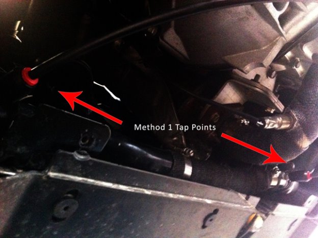
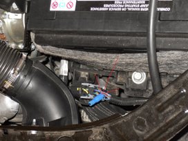
The pressure switch has two wires that will go to it, as well as the boost pressure hose. Let’s take a look at the hose. Again, the factory provided us with a nice location to take boost pressure. There is a boost port near the top of the driver’s side position on the intake manifold. It has a factory cap on it which must be CAREFULLY removed. Use a razor knife to remove the outer covering and then carefully pull the cap off with pliers. Then put the larger end of the included boost hose onto the fitting and the smaller end (it’s two hoses joined together) on to the boost inlet port on the pressure switch.
The arrows in the picture below show the two ends of the pressure hose. The bigger end goes onto the manifold. Take a good look at this picture to understand where the boost port on the manifold is located.

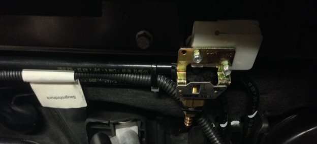
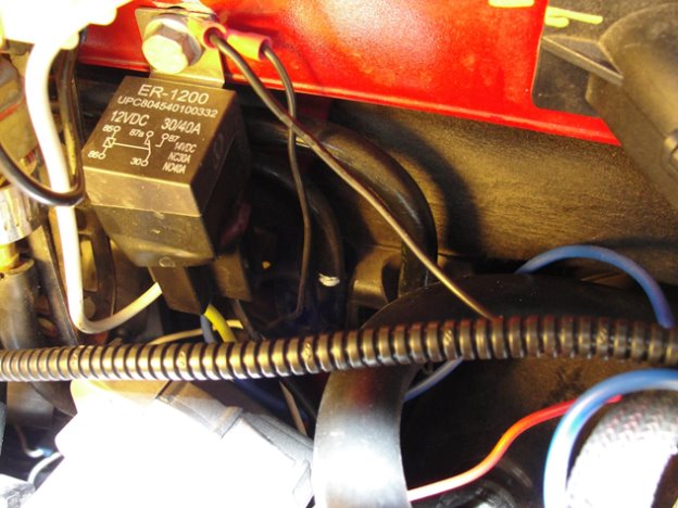
Mounting your relay: Use this existing ground point on the firewall to mount your relay next to the pressure switch, as shown below.
Wiring
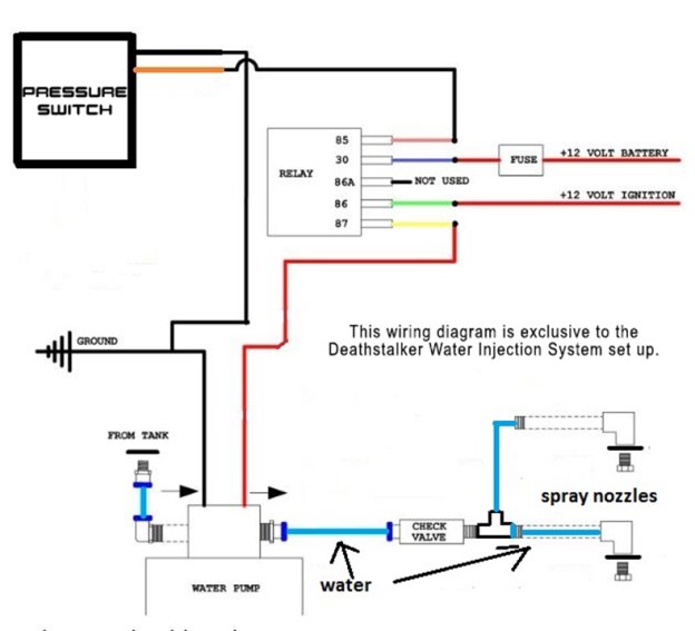
The wiring work is pretty straightforward. There are only four main wires associated with the system. They are Relay battery power, Relay to pump power, Relay ground, and Relay ignition supplied power.
The pump itself is powered by the most reliable power source in the car, which is the battery. Of course it can’t be connected directly to the battery or it would run all the time so a switching mechanism must be involved. The pump is switched on by a relay which connects a wire from the battery to the pump. The relay receives power continuously anytime the ignition switch is on. The relay’s ground wire is normally not grounded which prevents the relay from closing and sending power to the pump.
IMPORTANT NOTE: Do not rely on colors of the wires on the relay’s wiring socket. They are not consistent from one relay to another. You must look at the pin numbers on the underside of the relay itself.
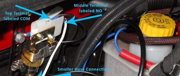
Next we need to attach the two wires to the pressure switch. The first wire is the ground wire. It connects to the top port labeled COM. The other end should ground via a ring connector to same bolt you mounted your relay to. The other wire connects to the connection point labeled NO. This goes to PIN number 85 on the relay. The Relay Socket/Harness already has wires on it. This particular wire has enough length, so just add a connector to it and plug it onto the NO point.
Battery Power:
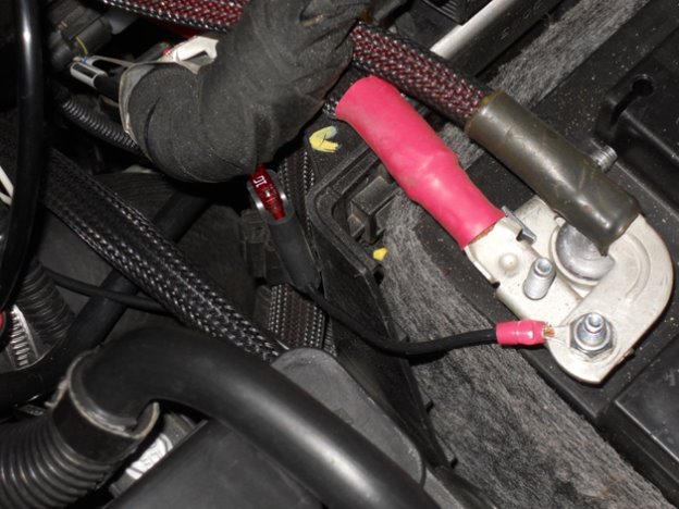
Next we need to connect the main power supply, the battery. Once again, Fiat has provided us with an excellent spot to take battery power. THIS WIRE MUST BE FUSE PROTECTED! Use the fuse holder with a ring connector on one end to attach to the nice location provided by Fiat on the battery terminal. The other end of the wire needs to connect to the wire from the relay socket going to Relay Pin 30. Take time and care to make sure you connect to the correct relay pins.
Pictured below is the fuse holder and fuse providing power from the battery terminal to Relay Pin 30.
The next wire will take power FROM Pin 87 on the relay to the Pump’s red power wire. Simply connect the pump’s power wire you brought up from the trunk and connect it to the wire on the relay harness coming from Pin 87.
Ignition Switched Power
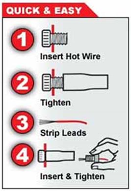
The next wire we will connect will deliver 12 volt power to the relay whenever the ignition switch is on. First we must learn about the wonderful new posi tap connectors. They allow tapping into wires without cutting or soldering the wire being tapped into, and they don’t cut or break the little strands of wire they tap into.
Study this diagram and understand the posi tap connectors before going any further. Steps 1 and 2 tap into the power wire, no cutting of that wire is required.
We are now going to connect PIN 86 on your relay to a source of 12 volt ignition power. First you will need to extend the wire so it can go all the way to the front of the battery box.
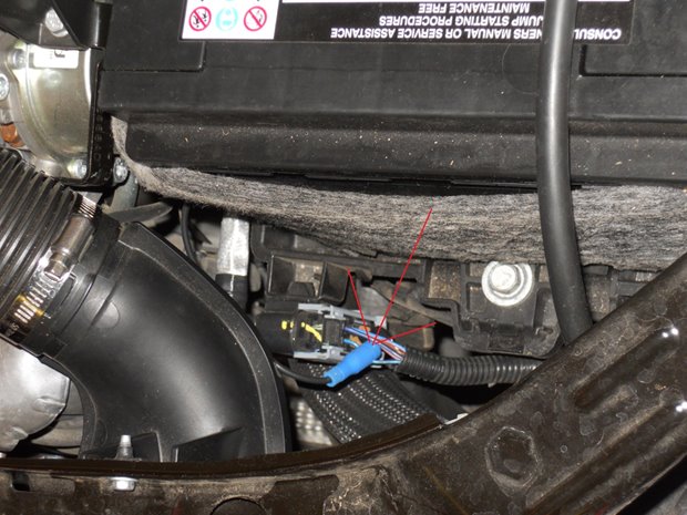
The wire we need to take power from is forward of the battery box. In the 2012 Abarth we used for these instructions, it’s the purple/light blue-green wire on the upper most forward position of the connector. If in doubt, use a test light and find a wire that has no power with the ignition off, but 12 volt power with the ignition switch ON.
Study this picture carefully. Use a posi-tap to connect to a 12 volt power source that’s only active with the ignition on. On the 2012 Abarth, it’s the wire pictured. On the 500 Turbo and newer Abarths, it’s most likely the same. This will provide ignition switch based power to Pin 86 on the relay.
Now, your system is fully operational. Double check everything and DON’T forget to put fluid in the tank before you run the pump! You can now test drive the car. At this point you don’t have the associated lights hooked up. However you can hear the pump turn on if you drive with the windows up, radio off AND fold the rear seat down. Adjust the pressure switch accordingly. To raise the activation pressure turn the wheel clockwise as viewed from above. To lower it, turn it counter clockwise. It will take a few tries to get it just right. HPSI suggests 10-12psi for the Abarth. After driving the car double check for leaks.
It’s worth pointing out, if you have the torque app or another way of monitoring intake air temps, you will see a large temperature drop when the system turns on.
Indicator Lights:
The indicator lights, needed connectors, and wiring are included. Installation and placement is optional but suggested. It’s important to be able to check operation by quickly glancing at the blue light, rather than by folding down the rear seat and listening for the pump. The red low level light indicates low tank level.
Optional Light Placement: Blue LED = System On Red LED= low fluid level in tank
You can install them anywhere you like, but this location is pretty easy to work with. The drawback is they are out of your normal line of sight. When the red light comes on there is going to be plenty of time to notice it and refill the tank. You only need to check the green light when making system adjustments or changes. It’s not something you monitor as you are driving.
Installing in the lights in this location is simple. The panel they are mounted in simply pulls off. Be careful as it’s plastic, but it’s not too much trouble to remove. (note, this particular car has the automatic temperature control system. You should be able to mount lights in a vehicle without climate control). The wiring in the lights isn’t long enough so you will have to extend them with extra wiring and connectors. They need to be long enough to reach the engine compartment. Label the wires so you know which wires come from which light.
Drill holes in the panel of your choice, taking care not to damage anything. Plan the holes so that the lights have enough room behind them to push all the way through. Again, drill small pilot holes first. Push the lights through. Thread the wires down along the left side of the console to the floor. There you will have to drill a small hole and pass the 4 wires through it. There is some insulation and carpeting you will have to move aside, but it’s easy. You must tuck all the wires out of sight where they won’t get caught on your feet or anything else. Once the wires are through, seal the area around them with silicone RTV or something similar. Make sure the wires can’t rub or vibrate against the sheet metal and be cut. A short to ground here could cause a fire!
Connecting the wires is going to be super easy. The Blue light has two wires. One must ground via a ring connector. I suggest grounding it to the firewall bolt where you installed the relay. The other wire connects via a posi tap to the pump’s power wire. The Blue light will now come on anytime power is sent to the pump.
The red light is equally easy. One of its wires must connect to the wire you brought up from the trunk coming from the low level switch. The other attaches via a posi tap to a 12 volt ignition switched power. You can tap into the factory wiring using a posi-tap connector.
The wire we need to take power from is forward of the battery box, and you’ve already posi tapped this wire once previously. Place a posi tap on the wire already posi tapped to this power wire.
Notes on Fluids:
Straight water will work fine as long as it’s free of impurities and has no danger of freezing. Distilled water, or water from a purifier will do the job.
The effective octane increase and resulting knock protection from pure water is more than adequate for this application. If you are using 91 (r+m)/2 pump gas with pure water you will have an effective octane of over 100 throughout all of the rpm range.
For additional knock protection and to protect against freezing, methanol can be added to the water. A 50/50 mix by weight is the most effective mixture. Don’t believe the internet hype about greater levels of methanol. Those were used in World War 2, but not for performance, it was to protect against freezing at 40,000 feet over Germany during the winter of 1944. A 50/50 mix is also safe as it’s not flammable.
A 80/20 water/methanol mix is very effective, and economical. This will protect from freezing down to 0F and offer an increase in anti-knock performance over straight water.
Do NOT use ethyl alcohol. That will actually reduce the anti-knock capability of the system as compared with just plain water! If you are curious, ethyl alcohol and water does have some advantages relating to air cooled engines, but that’s not what we are dealing with here.
Windshield Washer Fluids:
Do not use windshield washer fluid unless you know what you are doing. Many of these fluids contain chemicals we don’t want. However some are ideal, and they tend to be the cheaper fluids. Let’s learn to tell the difference.
At the time of this writing, Wal Mart’s SuperTech fluid is basically just water, methanol and about 1% dye and cleaner. That 1% makes it easy to see and keeps the nozzle clean. It’s about perfect for our purposes.
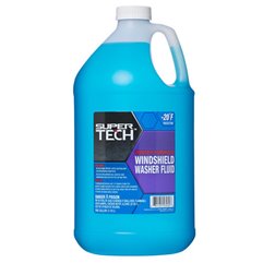
This stuff may be null as windshield washer fluid, but it’s ideal for water/methanol injection.
The lower the temperature rating, the more methanol. The lower temperature fluids tend to be seasonal and sold only in colder climates.
At the time of this writing the -20F version contains 31% methanol. 0F versions have 20%, which is an ideal choice. For comparison the +20F stuff has 10% and the +32F has on 1%. There are some lower temperature versions with 40% methanol, but sometimes they also have glycol which is bad. The IMPORTANT thing here is to check the MSDS before using it. They can change the formula they sell any time.
All hazardous chemicals sold in the US have a Material Safety Data Sheet (MSDS) associated with them that tells us exactly what’s in them. That sheet is typically on line at various retail outlets, and is required by law to be on hand at the actual store. However, the floor workers generally don’t know how to find them so I suggest checking yourself.
Let’s use Wal Mart as an example. Their website for MSDS is http://msds.walmartstores.com/ . Go there, search for supertech which is their house brand of washer fluids and pull up the MSDS. Look at the ingredients and if there are any hazardous chemicals other than methanol, DO NOT use it.
You can buy methanol at almost any speed shop. Just about anywhere they have a dynamometer they have methanol. Also many fuel system de-icers are just straight 100% methanol. Check the MSDS and add that if desired.
Our local speed shop sells Methanol for $3 a gallon. That makes a 50/50 mix about 1.50 a gallon, cheaper than windshield washer fluid.
You’re now ready to drive. Thanks for purchasing our kit.