THANK YOU
for purchasing the ND MX-5 Vent Gauge Pod Kit from CravenSpeed. This product is made from the highest grade materials, and is guaranteed to be free from defects.
You can buy our
CravenSpeed Vent Gauge Pod for ND MX-5 Miata here
Parts Included:
-
Your choice of Marshall Gauge (Oil Temp or Pressure)
-
Vent Gauge Pod Cup Kit
-
Tapless Oil Adapter Kit
-
2 ea Add-a-Circuit
-
2 ea 1 Amp Mini Blade Fuse
-
Green Wire 12 ft
-
Black Wire 4 ft
-
Red Wire 2 ft
-
Purple Wire 2 ft
-
4 ea Butt-splice Connectors
-
2 ea Ring Terminal
-
5 ea Ziptie
Tools Required:
-
Wire Strippers
-
Wire Terminal Crimper Tool
-
Trim Panel Removal Tool
-
10mm Socket and Ratchet Wrench
-
Awl or some other sharp thing to poke through the rubber plug on the firewall
Tools/Parts Recommended:
-
Soldering Station
-
Solder
-
Heat Shrink Tubing
-
Wiring Loom Tubing
The following instructions will walk you through the necessary steps of installing the adapters, sending units, and wiring to utilize the Marshall Oil Pressure and/or Oil Temperature gauges in your ND MX-5 Miata.
NOTE:
This document will focus on the actual wiring process of installing Marshall Gauges into your ND MX-5 Miata. Please completely read through the instructions before proceeding so that you become familiar with what is involved. You may also reference the installation instructions for the
Tapless Oil Adapter
and the
Vent Gauge Pod Mount
.
Let's get started
-
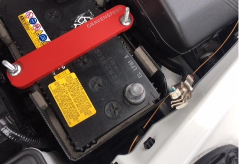
At this point, you should have the
CravenSpeed ND MX-5 Tapless Adapter
installed along with the particular sending unit (sensor) that your gauge configuration requires. You should also have the
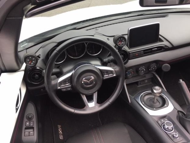
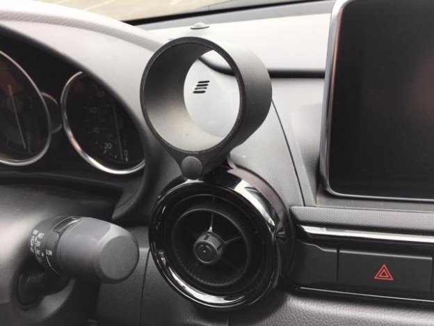
CravenSpeed ND MX-5 Vent Gauge Pod Mount
installed onto your dash with the empty gauge pod attached.
NOTE:
Please refer to the
Marshall Gauge Wiring Diagram
for more in-depth information regarding these gauges than what is provided within this guide.
-
When working on any part of the vehicle’s electrical system, it is always good form to disconnect the negative terminal from the battery to eliminate any possibility of accidental shorts or getting zapped. Pop the hood and do this now.
-
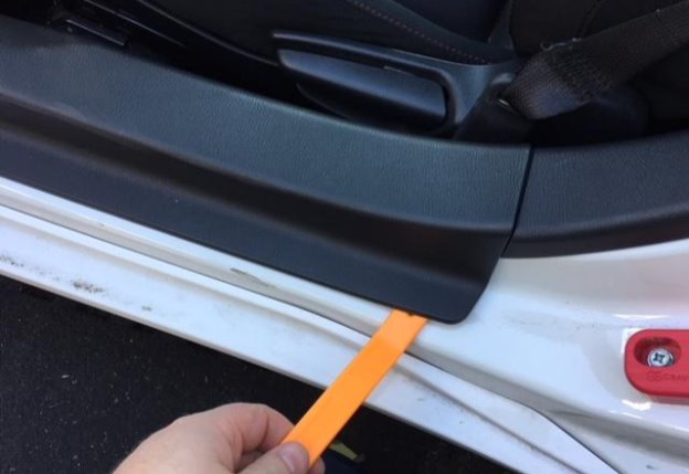
Open the driver side door and remove the door sill trim with your trim panel removal tool or similar non-scratching pry tool. It just disconnects straight up and off. You may even be able to just grasp it with your hands and pull up.
-
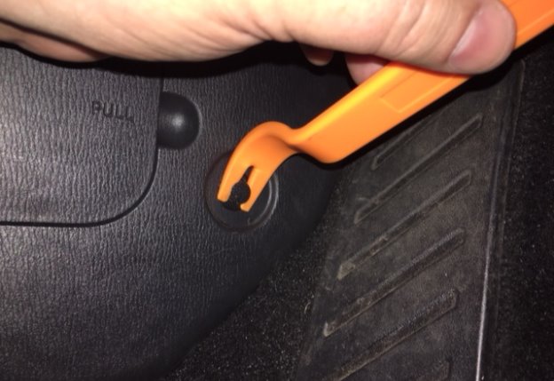
Remove the driver side kick panel. There is a plastic push-pin connector just forward of the fuse panel access hatch. A trim panel tool comes in handy here as well. Once the pin is out, peel the lower portion of rubber door seal off the pinch seam and pull the kick panel towards the back of the car. It should release without much effort.
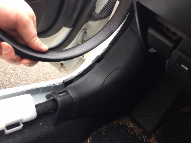
-
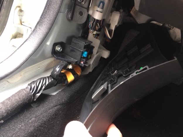
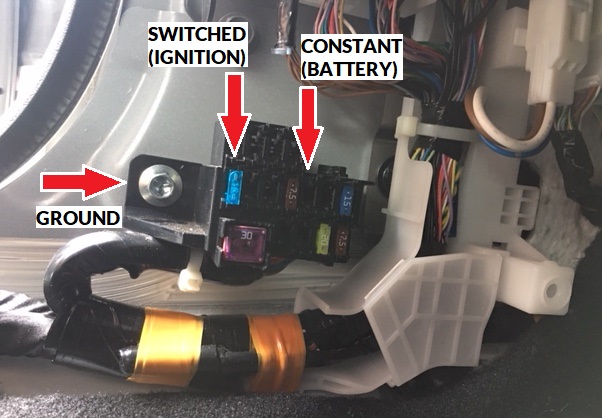
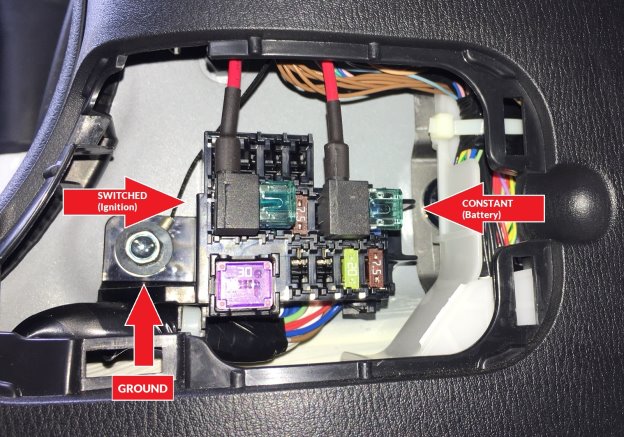
This will expose the fuse panel and allow access to the firewall behind the dash and routes for your gauge wiring. We’ll use the fuse slot locations shown in the image below for your power sources. The blue 15 amp fuse slot on the left is your switched power (ignition) and the empty slot just to the right of the brown 7.5 amp fuse will be your constant (battery). Your gauge will require both power sources and if you’re installing two gauges, they will share the power leads from each source. The 10mm screw to the left of the fuse panel will be your ground for the gauge(s).
-
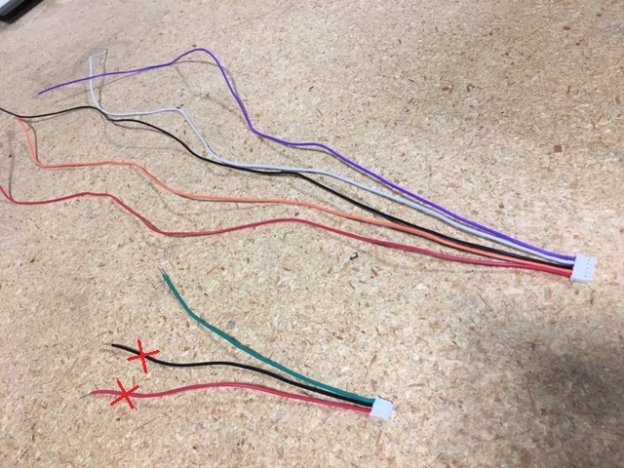
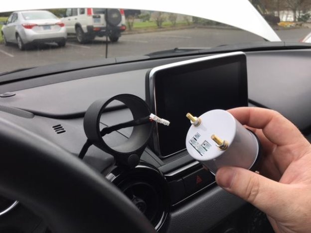
Open up the box that the Marshall gauge comes in and remove the wiring pigtails located at the bottom of the clamshell packaging. Separate them and set aside the 5-wire plug (Purple, White, Black, Orange, and Red) and the 3-wire plug (Green, Black, and Red).
-
The wire callouts are as follows: 5-wire plug;
Purple
= Constant Power (Battery),
White
= LEDS (white gauge illumination),
Black
= Gauge Ground,
Orange
= LEDs (orange gauge illumination), and
Red
= Switched Power (Ignition). The 3-wire plug is;
Green
= Signal lead to sending unit (Temp or Pressure Sender). The
Black
and
Red
wire are not used in this install, so you may trim them flush at the plug or just snip the exposed wire at the end and wrap a little electrical tape around them. If you’ve decided to mount a gauge on the right side of the steering wheel, we’ve included a few extra lengths of wire to allow these wire pigtails to reach the fuse panel. If you’re utilizing the left-side gauge mounting position, you’ll only need to lengthen the Black ground wire on the 5-wire plug and the Green wire on the 3-wire plug.
For right side mounting position;
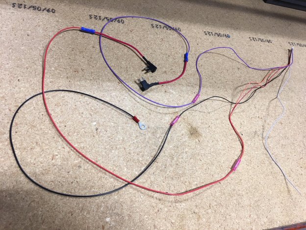
Take the 2 ft of purple wire provided in the CravenSpeed kit and using a butt-splice connector (or optional solder and heat shrink method) attach it to the end of the Purple wire on the 5-wire pigtail. Cut the 4 ft of Black wire provided in half and connect a 2 ft section of it to the end of the Black wire on the 5-wire pigtail. Next, you will need to decide which color of illumination you want (White or Orange LED). Take the color wire you decide and twist the end together with the Red wire of the 5-wire pigtail. Trim the exposed core from the unused LED wire and wrap a little electrical tape around it. Locate the 2 ft of Red wire included in your kit and splice one end onto the end of the Red wire/LED wire combination from the 5-wire pigtail. Crimp the ring terminal onto the end of the Black ground wire.
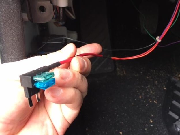
-
Now let’s connect our ‘Add-a-Circuits’. The Purple wire from the 5-wire pigtail gets connected to an ‘Add-a-Circuit’ and then install one of the provided 1 amp mini fuses into the top slot. For the remaining ‘Add-a-Circuit’, connect it to the Red wire from the 5-wire pigtail and add the remaining 1 amp mini fuse to the top slot.
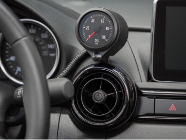
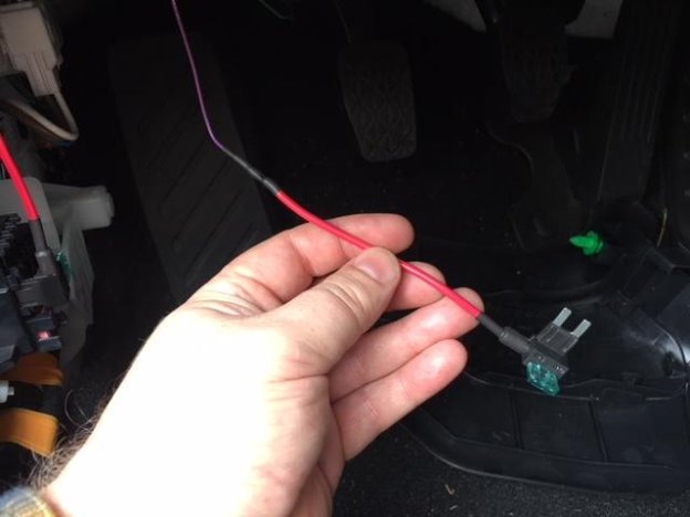
NOTE:
The image below shows the Orange LED wire being utilized leaving the White LED wire to be wrapped and tucked away.
-
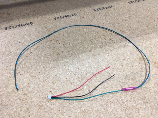
12 ft of Green wire is provided with the kit, but you’ll need to trim off 2 ft of that to add to the 3-wire pigtail. Again, the Red and Black leads from the 3-wire pigtail are not used, so trim the exposed wires and wrap them with electrical tape.
-
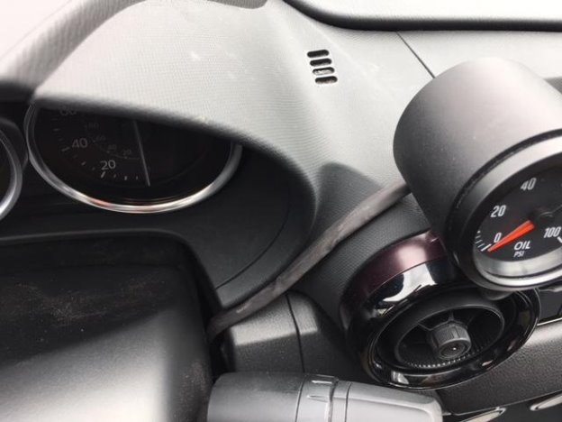
For aesthetic purposes, we recommend you combine these two extended gauge pigtails together within some wiring loom tubing (not included) and insert the wires through the dash at an upper location between the adjustable steering column and the dash. Fish the wire pigtails through the back of the gauge cup and plug the 5-wire pigtail into the lower 5-pin receptacle on the back of the Marshall gauge and the 3-wire pigtail into the receptacle just beside it.
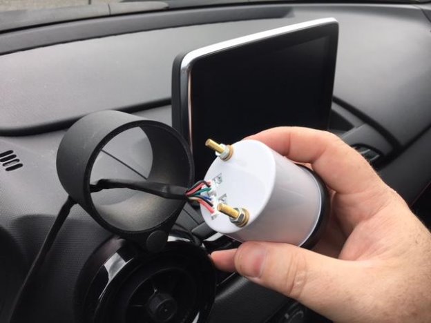
-
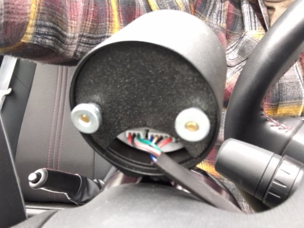
With the pigtail leads plugged into the back of the Marshall gauge, insert the gauge into the gauge cup and slide the ABS ‘half-moon’ cover onto the gauge mounting studs. Thread on the thumb nuts that came with the Marshall gauge. If the mounting studs seem a little long to you, utilize a rotary tool with a cut-off wheel and trim them to a more tidy length.
-
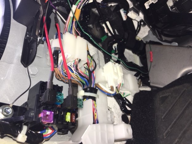
If you have not done so already, reach up into the dash underneath the steering console and pull both wiring pigtails through and over to the fuse box area. Locate and remove the blue 15 amp fuse in the switched power slot and place the 15 amp fuse into the lower slot on the switched power ‘Add-a-Circuit’ (red lead from gauge pigtail). Plug this ‘Add-a-Circuit back into the same slot on the fuse panel. Next, take the constant power ‘Add-a-Circuit’ with the 1 amp fuse you installed earlier (purple lead from gauge pigtail) and plug it into the empty fuse slot just to the right of the brown 7.5 amp fuse shown in the following images.
-
There is a 10mm screw located just to the left of the fuse panel which we will use for our gauge ground lead (black wire with ring terminal). Remove the screw, place the ring terminal onto it and reassemble.
-
The only wire left to connect is the green signal lead from the pigtails coming from the Marshall gauge. If you have the green signal wire from your tapless adapter sending unit already installed through the firewall, use a butt-splice connector and crimp the two wires together (green pigtail gauge wire to green signal wire from tapless adapter). Ziptie the wires under the dash so they are tucked out of the way and tidy.
NOTE:
If you do not have your green signal wire from your tapless adapter sending unit coming in through the firewall, follow the next steps.
-
As stated previously, you should have your sending unit for the particular gauge you’re utilizing already installed onto the Tapless Adapter that is mounted to the side of the engine block. See
ND MX-5 Tapless Adapter instructions
if you have not installed it yet.
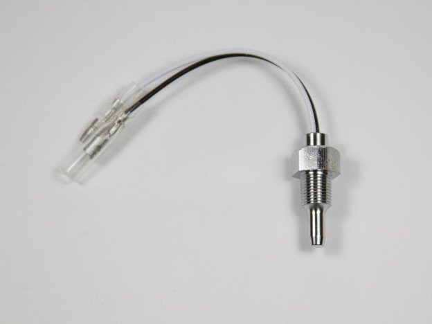
-
If you’re installing a oil temperature gauge, you will have a sending unit with a probe on one end and two wire leads on the other. The black wire is your ground and the white wire is your signal sending wire.
-
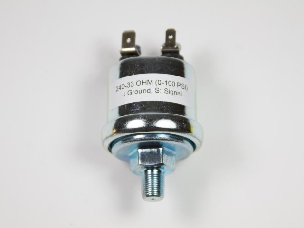
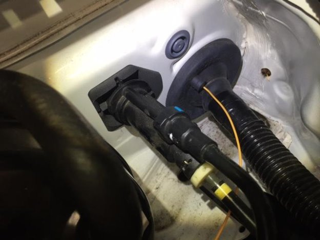
If you’ve mounted an oil pressure sender onto the Tapless Adapter you will have a unit similar to the image below. The two blade terminals on the sender housing are different widths, so take note of this when crimping the connectors onto the proper wires.
-
You should still have a 10 ft length of green wire. Crimp the supplied connector included with the Marshall gauge packaging onto your green wire and plug it into the white wire connector of the temp sender or the (S) blade terminal of the pressure sender.
Take note of the orientation and size of the plugs and don’t mix them up.
You should also have 2 ft of black wire left over from the interior install. Crimp the remaining connector onto the black wire and crimp a ring terminal to the opposite end. Plug these connectors into the leads/blades from the sender and then find a suitable ground for your black wire/ring terminal. We located a 10mm bracket screw some inches up and forward of the sender.
PLEASE NOTE:
In the following images, the signal wire used in our installation is
orange
. Your signal wire will be
green
.
-
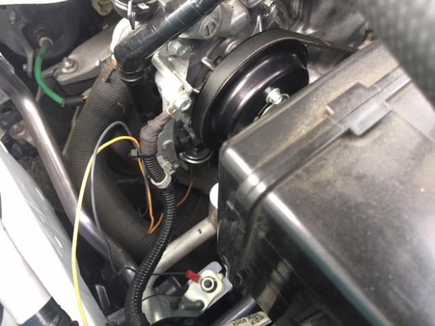
Bring your 10 ft green signal lead up and along the front core support of the vehicle, looping it behind the battery and then along side of the corrugated wiring loom. Ziptie the green wire in a few strategic locations to keep it out of the way of moving belts or components that may get hot.
-
Up at the driver side of the firewall there will be a rubber junction that the wiring loom travels through. There is a little molded ‘nub’ just above and to the side that we’ll pierce and feed the sender signal wire through and into the interior of the vehicle.
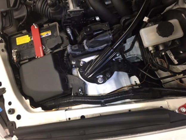
-
Go back to the interior and reach up into the back of the dash and pull the green sender wire through. Be sure to not pull too much and cause the wire in the engine compartment to become taunt.
-
Use a butt-splice connector and crimp the green signal wire from the Tapless Adapter to the green wire from the Marshall gauge. Ziptie the excess wire up and out of the way then reinstall your kick panel, door molding and trim.
-
Make a thorough check of the engine compartment to make sure all the wires are ziptied out of the way and no tools have been left lying around. Reconnect your negative battery terminal and start the vehicle. The Marshall gauge should turn on with the ignition and the needle should make a complete sweep then start reading normally. Take a flashlight and shine it down at the Tapless Adapter to make sure there are no oil leaks occurring. If everything checks out, go for a drive and marvel at the new bits!