THANK YOU for purchasing the F56 Tapless Adapter from CravenSpeed. This product is made from the highest grade materials, and is guaranteed to be free from defects.
You can buy our CravenSpeed Tapless Sender Adapter for MINI Gen 3 here
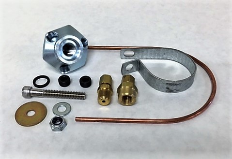
Parts Included:
- 1x Tapless Oil Adapter (Gen 3)
- 1x O-Ring
- 2 ea ⅛ NPT Pipe Plugs
- 1x ⅛ NPT Male to ⅛ Compression Fitting
- 1x ⅛ NPT Female ⅛ Compression Fitting
- 1x ⅛ Copper Line
- 1x Oil Pressure Switch Bracket
- 1x Socket Head Cap Screw SS 1.75L X ¼-20
- 1x Locknut ¼-20
- 1x Large Washer
- 1x Small Washer
- Teflon Tape (not included)
- Oil Pressure Switch and wiring or any related gauge components (not included)
Tools Required:
- Adjustable Wrench (capable of 1-½ size fasteners)
- 10mm Socket Wrench
- 3/16 Allen Key
- T25 Torx Driver
- 27mm Deep Well Socket
- Cordless Drill
- ⅛ Drill Bit
- Trim Panel Removal Tool (or similar tool)
***EXTREMELY IMPORTANT*** THE ENGINE MUST BE COLD PRIOR TO INSTALLATION OF THIS PRODUCT.
Procedure
Removal of the Oil Pressure Sensor
1. Remove the Air Intake Duct under the hood utilizing a 10mm socket.
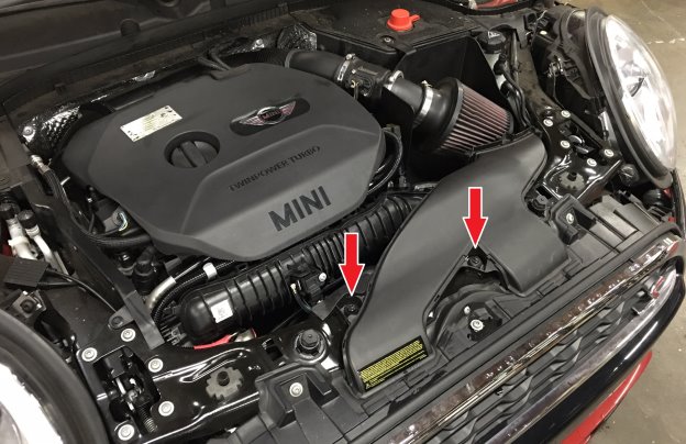
2. Pop the plastic engine cover off and set aside. It just pulls straight up and off.
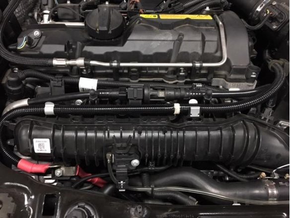
3. Disconnect the Fuel Tank Breather Line on the right upper side of the Intake Manifold. Pinch the connector together and pull off. Pull all the lines and wiring off of the Intake Manifold and keep track of the push on cable fasteners and where they’ll go upon reinstallation. There’s also a wire fastener attached to the underside of the Intake Manifold that goes to the Alternator. Pull it off as well. Hold these lines up and out of the way with a bungee cord or something similar so you’ll have unrestricted access to the intake manifold.
4. Unplug the T-MAP Sensor from the front of the Intake Manifold. If you have the PSIClone adapter already installed, just remove the entire assembly and let it hang out of the way. It is affixed with a T25 Torx screw.
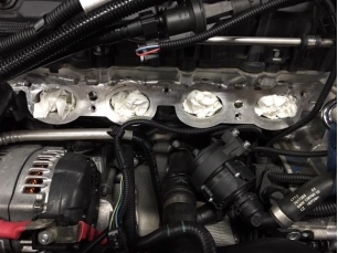
5. Remove the Intake Manifold via (5) 10mm hex bolts. Once lifted off of the engine, take 4 wads of paper towel and tuck them into the intakes so that nothing accidentally falls into them while you’re working around the engine. NOTE: DO NOT FORGET TO REMOVE THEM WHEN PUTTING THE INTAKE MANIFOLD BACK ON.
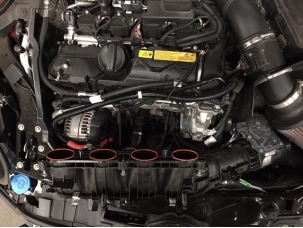
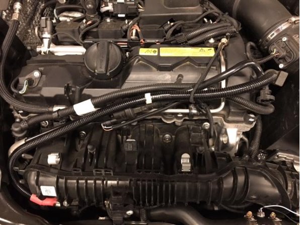
6. Disconnect the Intake Manifold and Throttle Body from the Charged Air Line Hose via wire quick disconnect and set aside. There are (2) wiring plugs connected to the underside of the Throttle Body that also need to be disconnected. NOTE: Do not lose any of the (4) Intake Manifold O-Rings that seal against the engine block.
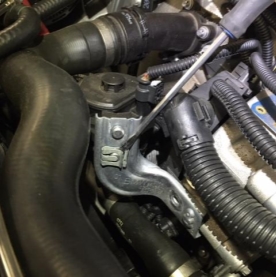
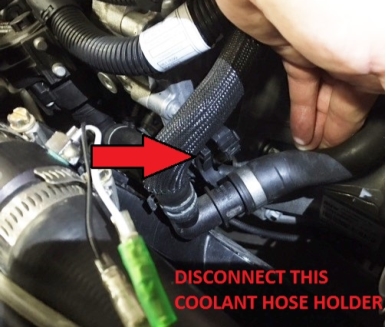
7. There is an ASA bolt that holds the Coolant Pump bracket (L-shaped) onto the front of the engine. Remove the bolt with a 10mm socket and set aside. Remove the (2) Circlips from the Coolant Pump and set them aside along with the L-bracket. The Coolant Pump will remain in the vehicle. There is a plastic coolant hose holder just to the right of the Coolant Pump that needs to be unclipped so that the hose can be lifted up and out of the way.
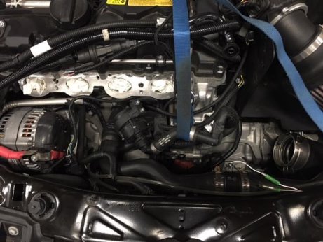
8. Use a nylon strap and loop it underneath the coolant hose and pull it up and out of the way so that you have the room to access the Oil Pressure Sensor.
9. Unlock the Oil Pressure Sensor wiring plug and disconnect it from the sensor.
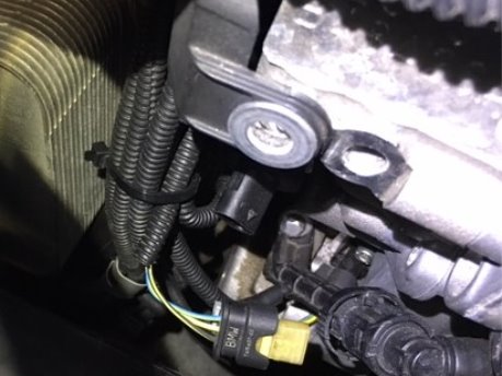
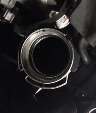
10. Utilizing a 27mm deep well socket, remove the Oil Pressure Sensor. There will be a small amount of oil that will come out once the sensor is removed, so just wipe it up with some paper towel.
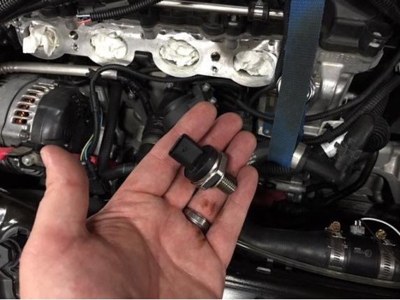
Installing the Tapless Oil Adapter
1. Install the O-Ring included with your Tapless Oil Adapter over the threads till it seats against the body of the adapter. Do not install the factory Oil Pressure Sensor onto the adapter just yet. We still need to determine the port that will be used for the compression fitting.
2. Thread the Tapless Oil Adapter onto the engine block hand tight. Take note of which hole is in the 1 to 4 o’clock position as this is the hole that you’ll be threading the compression fitting into. Mark the hole with a Sharpie pen or something similar.
3. Remove the Tapless Oil Adapter and fit the (2) included plugs into the unused holes. Wrap the plugs with a little teflon tape before installing them. Wrap the male compression fitting with teflon tape and install it into the threaded port you selected when hand-fitting the adapter onto the engine. NOTE: Due to limited space, it may be necessary to install the compression fitting AFTER the adapter has been fully seated onto the engine block.
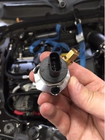
4. Now install the factory Oil Pressure Sensor onto the Tapless Oil Adapter and tighten. Install the completed assembly onto the front of the engine and tighten with your adjustable wrench. Make certain the O-Ring was fitted onto the Tapless Oil Adapter before installing it. Space is a bit limited during this procedure, so take it slow and be careful of the surrounding wires as you tighten it into place.
5. Plug the Oil Pressure Sensor wiring back on and engage the lock.
Installing the Copper Line and Oil Pressure Switch
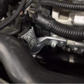
1. Take the included Oil Pressure Switch Bracket and install it onto the tab hole on the transmission housing. Order of parts assembly is; Cap Head Screw>Small Washer>Switch Bracket>Transmission Tab>Large Washer>Locknut. See image for orientation.
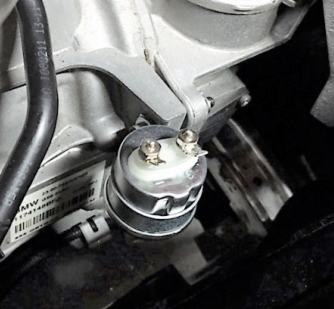
2. Wrap the threads of the Oil Pressure Switch (not included) with some teflon tape and install the female compression fitting. Temporarily set the Oil Pressure Switch into the included bracket and form the Copper Line so that it connects both compression fittings. Create a gentle bend so the line isn’t stressed from engine vibration. If necessary, cut the Copper Line to its required length and confirm that it is free of any burrs or debris.
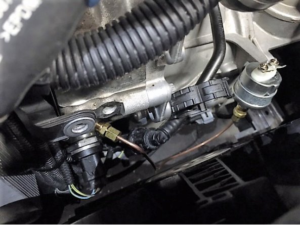
3. Once you have the copper line formed to your required shape, remove the Oil Pressure Switch from the bracket, insert the line back into the compression fitting and tighten the collar. Install the Oil Pressure Switch back into the bracket and tighten. Insert the other end of the copper line into the Tapless Oil Adapters compression fitting and tighten the collar. Make sure it is fully seated and take care to not over tighten and strip the brass fittings.
4. Attach your ground and signal wiring leads (not included) to the Oil Pressure Switch taking note of the polarity. We’ll be going through the rubber firewall plug on the driver’s side of the firewall, so we want to head that direction with the wires. Periodically zip-tie them into place to keep them secure.
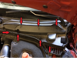
5. We’ll be drilling through this firewall plug, but to gain better access to the area we need to remove some trim components from the engine compartment first. There is a plastic cowl apron cover on the driver’s side that needs to be removed along with the water drain. The apron cover has (4) quarter-turn fasteners, (2) 10mm plastic nuts and a center mounting clip holding it into place. The water drain is just set into place and can be easily lifted out.
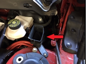
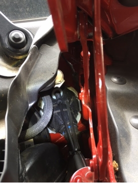
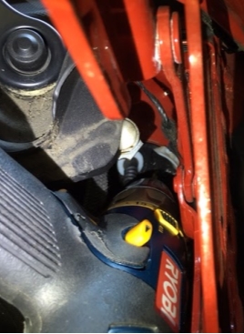
6. There is a flat section on the rubber firewall plug, just below and to the right of the hood release cable, that we will be drilling through. Use your cordless drill with a ⅛ drill bit and carefully drill through the firewall plug, being careful to stay centered within that flat area. The plug is comprised of a hard white nylon core surrounded by the softer black rubber.
7. Remove the driver’s side trim panel on the side of the dashboard with the trim panel removal tool.
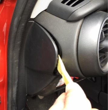
8. With the trim panel removed, take a flashlight and look inside, back toward the firewall. You should see the hole you just drilled through the firewall plug. Go back to the engine compartment and feed the Oil Pressure Switch wires through the drilled hole. Back to the dash, and this may be a tremendously tight squeeze, but reach in and continue to pull the end of the wires through the firewall plug making sure they retain some slack in the engine compartment.
9. Replace the right side water drain and cowl apron cover.
10. Reassemble the engine compartment components.
11. You are now ready to start wiring up the Oil Pressure Gauge. We recommend you now take a few moments and familiarize yourself with the installation instructions included with your aftermarket gauge.