THANK YOU for purchasing the MINI Gen 1 ScanGauge II Mount from CravenSpeed. This product is made from the highest grade materials, and is guaranteed to be free from defects.
You can buy our CravenSpeed ScanGauge II Mount for MINI Gen 1 here
Parts Included:
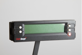
- 1x ScanGauge II Module
- 1x Bracket Z
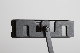
- 1x Tibia Flextension Arm
- 1x Button Head Screw
- 1x Flat Head Screw
- 2 ea Plastite Screws
- 2 ea Plastic Spacers
- 2 ea Plastic Washers
- 2 ea Metal Washers
Tools Required:
- Philips Head Screwdriver
- T-25 Torx driver
- (optional) 5/32" Hex Driver
- (optional) 7/16" Wrench
Procedure
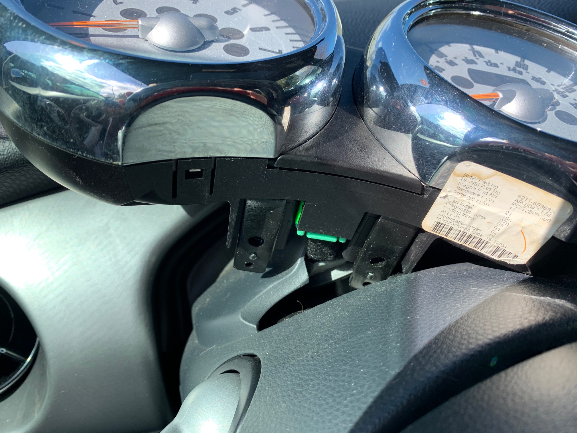
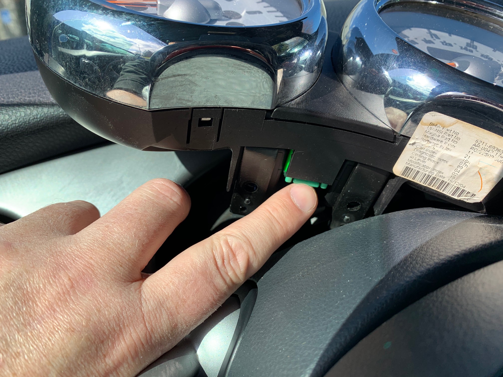
1. Remove factory mounting screws behind tachometer using the T-25 Torx driver. Set them safely aside as you will be reinstalling them.
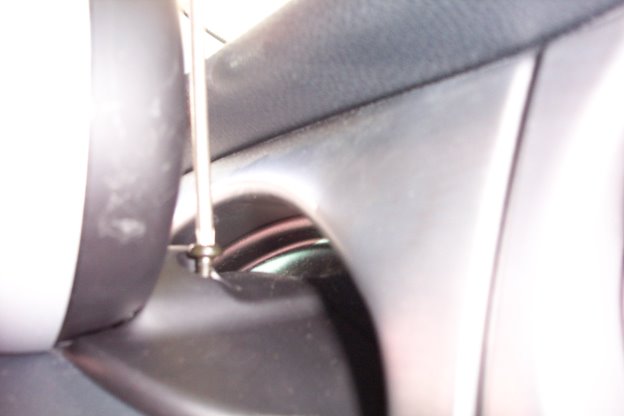
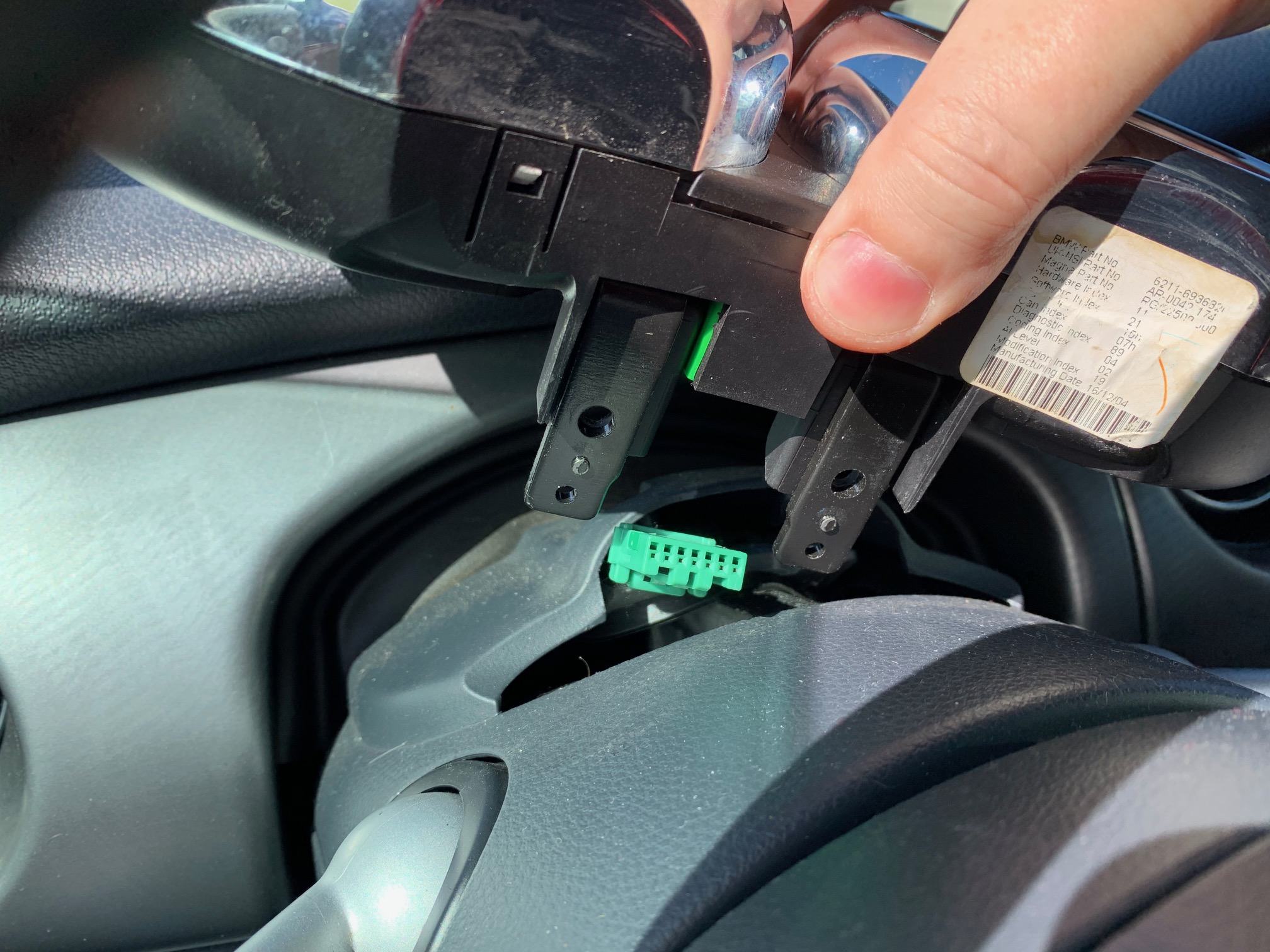
2. Lean the tach towards the steering wheel to gain access to the screws on the backside of it. Alternatively, you may also disconnect the gauge cluster from the wiring loom and perform this installation on a work surface. Press the locking tab on the green plug and lift the gauge cluster off of the steering column.
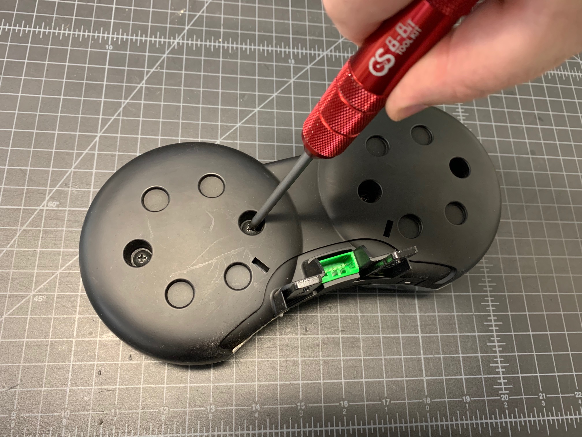
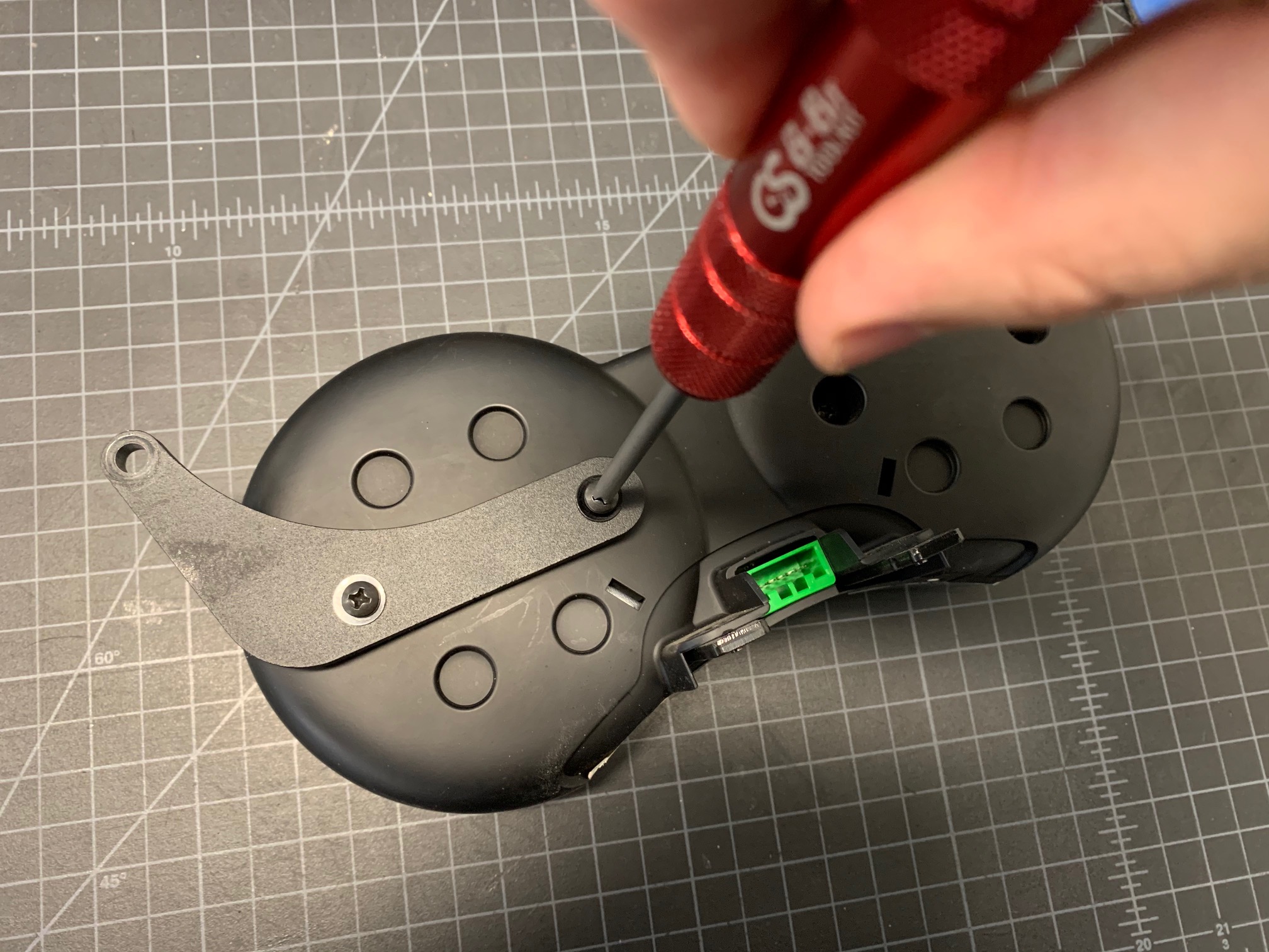
3. Using the Philips Head Screwdriver, remove the two screws on the back cover of the tach. You may wish to keep the OEM screws, but you will not need them for this install.
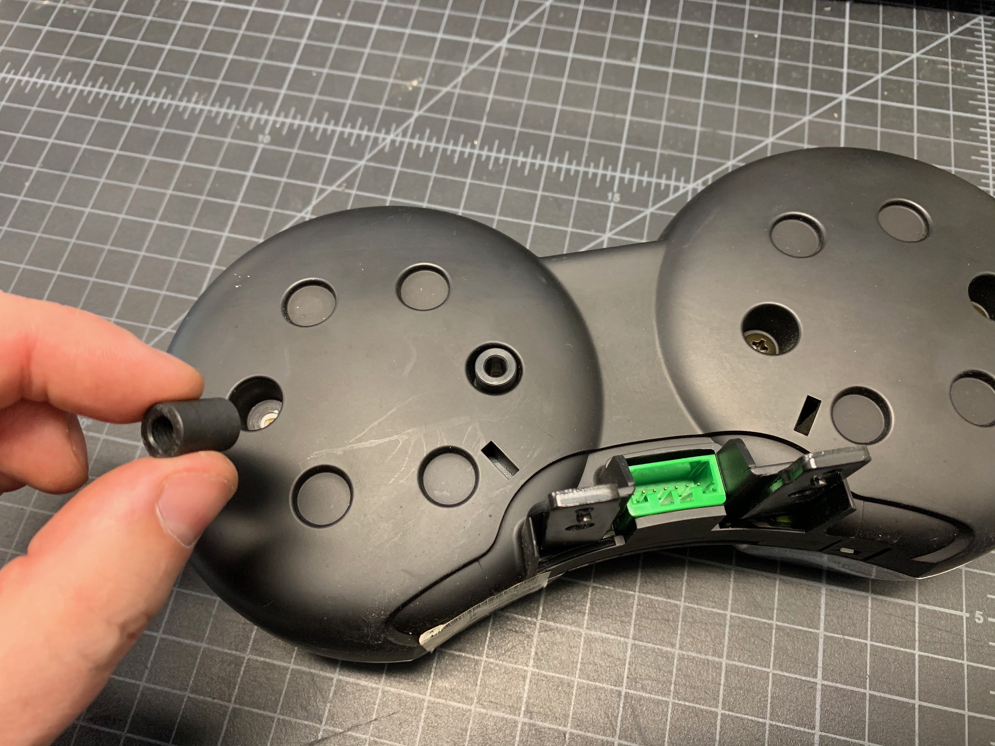
4. Place the 2 Plastic Spacers into the holes where the tach housing screws were removed.
NOTE: This product is pre-assembled in the standard right-facing orientation, but it may be easily configured for left-side use as well.
5. Place the Bracket Z so that the mounting holes line up with the 2 Plastic Spacers and position it so that the Tibia Flextension Arm is pointing up and depending on your preference, facing either the left or right side of the tach. If you decide upon a left-sided configuration, utilize a 5/32 Hex Wrench and a 7/16 Nut Driver and remove the Tibia Flextension Arm (with the ScanGauge II Module still attached) and place it on the opposite side of the Bracket Z.
6. Affix the Bracket Z with the included Plastite Screws and Metal Washers. Make sure the bracket is solid, but do not over-tighten.
7. Place the tach back in its original position and reattach it with the factory T-25 Torx screws.
8. Place your ScanGauge into the cradle making sure the 4 end ‘tabs’ fully engage the slots in the ScanGauge housing and adjust to the desired position.