THANK YOU for purchasing the MINI Complete Gauge Pod Kit - Gen 3 from CravenSpeed. This product is made from the highest grade materials, and is guaranteed to be free from defects.
You can buy our CravenSpeed Complete Gauge Pod Kit for MINI Gen 3 here
Parts Included:
- 2 Gauges requested: (Boost/Vac / Coolant Temp / Oil Pressure / Oil Temp / Volts)
- All Necessary Wiring and Senders
- All Necessary Sender Adapters and Hardware
- Gauge Pod Mounting Bracket and Hardware (3ea Phillips Screws)
- 2 Gauge Pods and Hardware
Tools Required:
- Phillips and Flat-head Screwdrivers
- T20 T25 and T30 Torx Drivers
- 3/16" Hex Driver
- Ratchet Wrench with Metric Sockets
- Adjustable Wrench
- Trim Panel Removal Tool (standard screwdriver will work with care)
- Cordless Drill with 3/16" and ¼" Drill Bits
- Rotary Tool with Cut-off Disc Attachment (Dremel)
- 12v Test Light
- Wire Strippers
- Wire Connector Crimper Tool
- Hose Cutter (coolant gauge install only)
Before you start, please completely read through all the instructions so you may get an idea of what is involved during this installation process. If it appears to be beyond your ability, please seek out qualified individuals who may assist you with the installation. These instructions contain a majority of the information required to install a variety of gauges, but some of the information may not relate precisely to your setup, so please keep that in mind.
• ALWAYS WEAR SAFETY GLASSES
• Install sender adapters and gauges only when engine is cool and ignition is off.
• Make sure all necessary parts, tools and related materials are on hand before beginning.
• Disconnect the negative (-) battery cable before working with any part of the vehicle’s electrical system.
• Make sure gauge mounting location does not impair visibility or interfere with your driving.
• If you must drill, always check and be aware of what’s behind your drilling surface. You don’t want to mistakenly damage any wiring or components.
Procedure
Installing the Gauge Pod Bracket and Pods
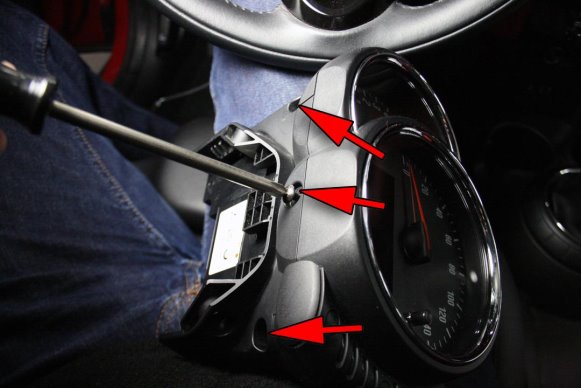
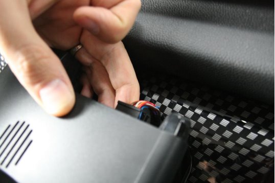
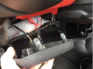
1. There are two screws hiding underneath little caps, holding the factory instrument cluster in place. First remove the caps and then the screws--one on each side. Use T20 Torx Driver.
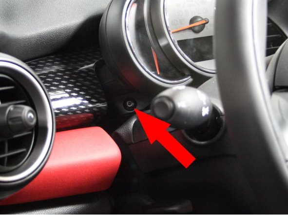
2. Slide the instrument cluster towards you and unplug the wiring from the back to free it from the steering column.

3. There is a small lock-tab on the connector that can be a bit stubborn, so be patient so you don’t break the lock-tab.
PLEASE NOTE!: On cars with heads-up-display (HUD), there will be an additional wire that can not be disconnected. Installation will have to be done more carefully as to not to put too much stress on the wires.
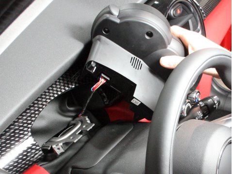
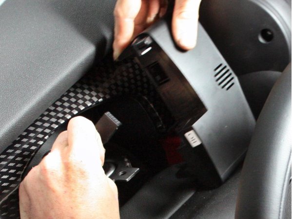
4. Using a Phillips head screwdriver, remove the 3 screws from the bottom of the instrument cluster.
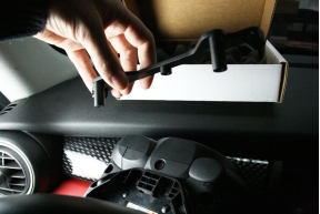
5. Now take the main bracket from your CravenSpeed FlexPod Gauge Mounting Kit and place it on the bottom of the instrument cluster so that the posts of the bracket line up with the screw holes. Using the screws provided with your kit, attach the bracket to the instrument cluster. Note: These screws are slightly thicker than the OEM screws and all three are the same length. Once the bracket is secure (no wiggle), do not continue to tighten as this will just strip out the plastic housing.
6. Re-connect the instrument cluster wiring, set it back into place on the steering column and reinstall the T20 screws on both sides.
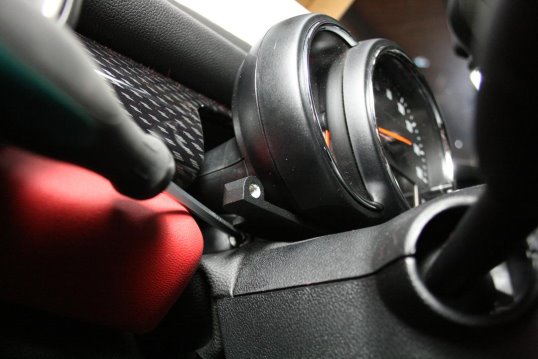
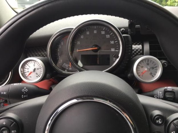
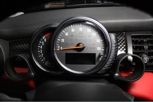
7. Utilizing a 3/16 Hex driver, attach the gauge pods to both mounting points using the included socket head cap screws and plastic washers.. Insert the plastic washer between the pod and bracket mounting surface.

8. Install the hole plugs over the socket head cap screws for a nice, clean look.

9. Voila! You’re on your way. Now the real adventure begins!
Installing the Power Wires for the Gauges
Let’s dive into the fuse box to determine our power tap points.
Marshall Gauges require both a constant battery power and a switched ignition power in their wiring installation. The fuse box in the F56 MINI is located above the front passenger side footwell and we’ll be utilizing a couple of the vacant fuse slots to power the gauges.
1. Access the fuse box by depressing a tab on the lower left corner and releasing it from the firewall. There are 2 tabs on the right side of the fuse box that engage mount points on the firewall.
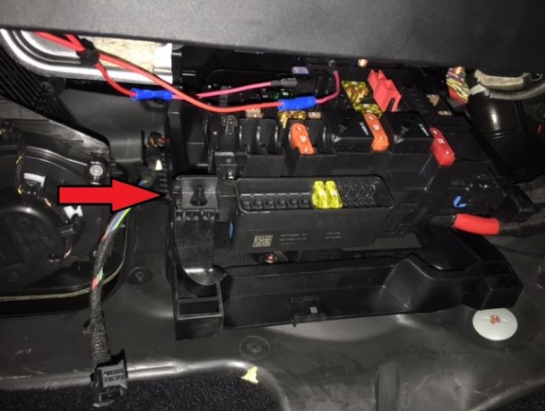
2. The fuse box has some rows that are constant (battery) power and some that are switched (ignition) power. Use your 12v test light to determine which ones are available for your ‘Add-a-Circuits’. We were able to use slot #87 for constant (battery) and slot #50 for switched (ignition). NOTE: If it is still there, refer to the paper fuse chart that is folded up and stored into a slot in the middle of the fuse box.
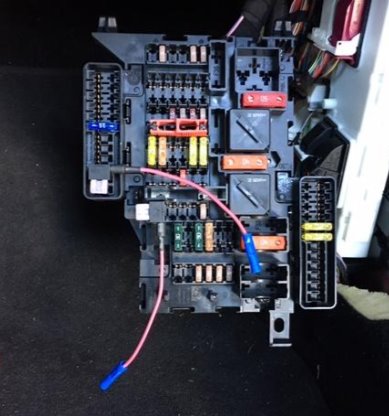
3. Locate the 10ft length of 18 awg RED wire included with your kit and cut it in half so you are left with two equal length pieces of approx 5ft each. Strip the insulation from one end of each of them and crimp them onto the end of their own ‘Add-a-Circuit’. For ease of wiring them to the gauges, label each power lead with how it has been configured (Constant or Switched power). NOTE: See enclosed instructions for the ‘Add-a-Circuit’ to familiarize yourself with their fuse configuration. Once you’ve determined the fuse slots you’re using and have plugged in the ‘Add-a-Circuits’, rotate the fuse box back up into position and reinstall it. Be sure you’ve engaged the tabs on the right edge of the fuse panel assembly with the corresponding mounting slots on the firewall.
4. Next, we’ll remove both the driver and passenger footwell, center console panels. Using the T20 Torx driver, remove the upper center screw then give the panel an outward tug to release it from the center console. They should just pop right off. Be aware of the footwell lights that are plugged into each panel. You can either unplug the lights and set the panels aside or allow them to remain plugged and just work around them.
5. Take your power wires and feed them through the center console, strategically zip-tying them to keep them tucked up and out of the way. Be mindful of where you route them so that the footwell panels can be reattached to the center console without causing interference from the wire placement.
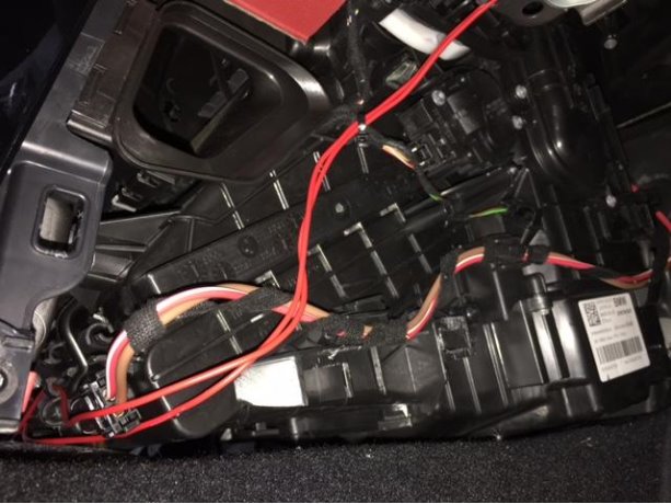
6. Move over to the driver side footwell and take up the slack in the power wires. Route them up and along the driver side of the footwell, avoiding the heater core tubes then zip-tying them into place so they’re out of the way of the panel’s mounting points.
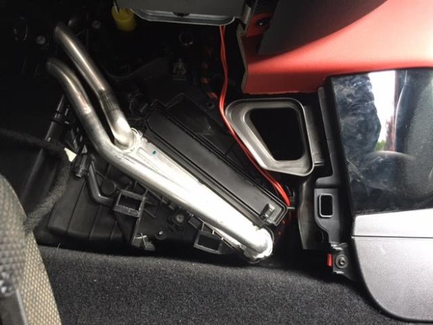
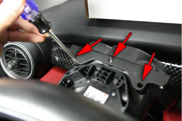
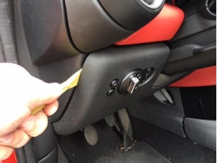
7. Utilizing the Trim Panel Removal Tool, first loosen the edge of the side dash panel then pop off the lower dash panel that is located below the steering column. Removing this panel will allow the access necessary to route the power wires through the dash area and connect them to the gauges. NOTE: Be careful of the wiring plugged into the back side of the headlights control panel. Take a moment to unplug this and set the panel aside.
8. Continue to feed the power wires through this space beneath the steering column and out through the opening on the left side.
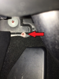
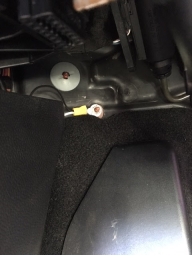
9. Now we’ll install the ground wire that the gauges and various senders require to function. Included with the kit should be a 3 ft length of 18 awg black wire, a ring terminal and a M5 K-lock nut. Our recommended ground point for all the gauges and senders is against the driver’s side firewall just above the dead pedal. Use the included M5 K-lock nut to attach your ring-terminaled ground wire to this point. Crimp a butt-end connector onto the other end of your ground wire and tuck it out of the way of the footwell and through the opening in the lower dash.

10. With both power wires and ground wire installed, labeled and ready to go, we’ll now proceed with the installation of the various adapters and sending units your gauge kit will utilize.